 Facebook
 Google
 GitHub
 Linkedin
Hi,
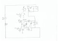
I have attached an schematic which I took from a board. I followed the board lines and that's what I got.
That circuit is used to control an incline motor those that you can find in a treadmill.
I'm having hard time trying to understand that circuit. I have read information on the web, but still got my wires crossed. Maybe I'm not understanding well triacs and opto triacs with zero crossing circuit.
Could anyone help me understand the principle of this circuit? How is the transition between the inductors? As it is from a treadmill, the motor goes up and down depending on the inductor energized.
I would appreciate your comments.
Attachments
-
 67.6 KB Views: 22


