 Facebook
 Google
 GitHub
 Linkedin
In this case using a 74HC02 at 2V
Simple needs:
Gate 1 > Drive an LED at 2mA @ 2V output
Gate 2 > Drive a Transistor with the 2V output. Saturation is about 3mA.
The datasheet here: http://www.nxp.com/documents/data_sheet/74HC_HCT02.pdf?
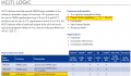
From NXP selection guide in the screenshot it says 8mA. I can't find 8mA anywhere to confirm.
Then:
If you look at something like this- https://gadgetory.com/index.php?route=product/product&product_id=82 it says 5.2mA for 2 to 6v.
So from the datasheet:
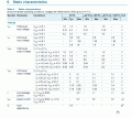
Is it a maximum of -20uA at 2.0V, but then if you look at 6V you also have -20uA and further down -5.2mA or is this the voltage at those currents. But where is the actual source sink currents.
If you look at the 'limiting values'
Io - Output current - -0.5 < Vo <Vcc + 0.5V +- 25mA
Icc - supply current 50mA
I interpret that as It can supply 25mA out of any output pin as long as 50mA is not exceeded. So: 20uA, 25mA, 5.2mA, 8mA ???
Simple needs:
Gate 1 > Drive an LED at 2mA @ 2V output
Gate 2 > Drive a Transistor with the 2V output. Saturation is about 3mA.
The datasheet here: http://www.nxp.com/documents/data_sheet/74HC_HCT02.pdf?
From NXP selection guide in the screenshot it says 8mA. I can't find 8mA anywhere to confirm.
Then:
If you look at something like this- https://gadgetory.com/index.php?route=product/product&product_id=82 it says 5.2mA for 2 to 6v.
So from the datasheet:
Is it a maximum of -20uA at 2.0V, but then if you look at 6V you also have -20uA and further down -5.2mA or is this the voltage at those currents. But where is the actual source sink currents.
If you look at the 'limiting values'
Io - Output current - -0.5 < Vo <Vcc + 0.5V +- 25mA
Icc - supply current 50mA
I interpret that as It can supply 25mA out of any output pin as long as 50mA is not exceeded. So: 20uA, 25mA, 5.2mA, 8mA ???
Attachments
-
 121.6 KB Views: 10
 -
 36.3 KB Views: 10


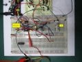
 yes I know I can make the smoke escape, and it will probably run an LED if I also hook it up to my house hold mains. At least for one billionth of a nano second, but it should work


