Ultrasonic Receiver Circuit Not Working (SOLVED)

Ian0

Joined Aug 7, 2020
13,158
Do you know other ampOps that would work better? I could use only analog data to arduino but I'm afraid that more gain will also mean it will amplify the noise higher and maybe get the comparator saturating positively when there's no sign... since in the last tests it amplified to 5V whenever there was noise.
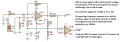
There’s plenty. They usually go by their GBW product, so if you want a gain of 100 @ 40kHz, you need a GBW product of 4MHz minimum.
One I’ve been using that might do the job is he Microchip MCP6024.
If it gets too noisy, then that’s your limitation. You will have to transmit more power, or improve the filtering and noise on the receiver.
[Edit] Corrected the Microchip part number.
 
Last edited:

Audioguru again

Joined Oct 21, 2019
6,826
1) The slow LM324 barely works at 40kHz. Also its input current causes a DC voltage across R7 which makes the amplifier output to go high. The original circuit used a TL084 that has Jfet inputs with no input current.
2) Get rid of the breadboard! Its messy wires all over the place are antennas that pickup all kinds of interference. Also the capacitance between the wires and between the rows of contacts cause a high gain amplifier of oscillate.
3) The original circuit used a fast TL084 opamp that has no input current. BUT its minimum supply is 8V or 10V and many do not work properly when the supply is only 5V.

Why do you think the receiver amplifier will detect the 40kHz or not? The circuit has no detector, the output will go high, low, high, low when there is a signal, interference or IC noise. When the output is producing 40kHz, interference or noise, the LED will appear to be continuously lighting.
 

Attachments

Ian0

Joined Aug 7, 2020
13,158
A couple of other points:
I don’t know how sharp the resonance is, but it might be worth tuning the frequency for maximum output.
I wonder if 3.9k is rather too low a load resistance for what is a crystal transducer.
 

Audioguru again

Joined Oct 21, 2019
6,826
The 40kHz piezo transducer needs a high resistance load (100k or more) and a shielded audio cable to block interference.
The lousy old LM324 shows a typical gain of only 25dB at 40kHz on the graph on its datasheet. ICs with minimum specs will have less gain.
25dB is a voltage gain of only 17 times and the poor slew rate also reduces the gain.
 

Ian0

Joined Aug 7, 2020
13,158
Don't use an op-amp as a comparator! Some may work, and some don't. The TL071 series is a good example. It suffers from phase reversal when driven into clipping.
 

Audioguru again

Joined Oct 21, 2019
6,826
The TL08x has the same specs and phase reversal problem as the TL07x opamps.
Hey, maybe the phase reversal when an input voltage gets within a few volts of the negative supply (ground in this circuit) causes rectification of the ultrasonics?
 

ericgibbs

Joined Jan 29, 2010
21,460
Hi didifi,
Lots of posts, but the bottom line is that using your Arduino ADC sampling program and comparing the sample rate and 40kHz Sine wave, you can see the real reason your ADC output is fluctuating.

Use the 1k/100k modification that was posted to ensure the correct Vo offset.

Look at the LTS plots of the way your Sketch is hit-and-miss sampling at an approx 90mSec rate, which will give the fluctuating readings.[V(vo)+V(smp)] plot line

E
EG57_ 811.png
 

Ian0

Joined Aug 7, 2020
13,158
Not everyone on this forum can interpret an ino file, so the rest of us (with the exception of @ericgibbs ) missed the fact that your sampling rate was far too low.
Either:
sample more than twice the signal frequency 80,000 samples per second
Or:
rectify the output signal and sample that.
or:
trigger a monostable with the first output from the comparator, and read that as a gpio input.
 

Ya’akov

Joined Jan 27, 2019
10,258
Not everyone on this forum can interpret an ino file, so the rest of us (with the exception of @ericgibbs ) missed the fact that your sampling rate was far too low.
Either:
sample more than twice the signal frequency 80,000 samples per second
Or:
rectify the output signal and sample that.
or:
trigger a monostable with the first output from the comparator, and read that as a gpio input.
To paraphrase, “Men plan, Nyquist laughs.”
 

Ya’akov

Joined Jan 27, 2019
10,258
Cry God for Harry??
I have to admit that, though I recognize the quote from the Bard, I don’t understand the reference. I was paraphrasing, what I know to be an old Yiddish proverb:

דער מענטש טראַכט און גאָט לאַכט
Der mentsh tracht un got lacht.

This means, ”the man plans and God laughs”. You made me question the provenance of it, but looking around a bit I can’t find any other source. Please explain your reference, though (and thanks for having me review Henry V, I don’t spend much time reading Shakespeare and he’s—they’re (?)—really inspiring as a writer.
 

Ian0

Joined Aug 7, 2020
13,158
I have to admit that, though I recognize the quote from the Bard, I don’t understand the reference. I was paraphrasing, what I know to be an old Yiddish proverb:

דער מענטש טראַכט און גאָט לאַכט
Der mentsh tracht un got lacht.

This means, ”the man plans and God laughs”. You made me question the provenance of it, but looking around a bit I can’t find any other source. Please explain your reference, though (and thanks for having me review Henry V, I don’t spend much time reading Shakespeare and he’s—they’re (?)—really inspiring as a writer.
Harry Nyquist!
 

Thread Starter

didifi

Joined May 8, 2023
31
1) The slow LM324 barely works at 40kHz. Also its input current causes a DC voltage across R7 which makes the amplifier output to go high. The original circuit used a TL084 that has Jfet inputs with no input current.
2) Get rid of the breadboard! Its messy wires all over the place are antennas that pickup all kinds of interference. Also the capacitance between the wires and between the rows of contacts cause a high gain amplifier of oscillate.
3) The original circuit used a fast TL084 opamp that has no input current. BUT its minimum supply is 8V or 10V and many do not work properly when the supply is only 5V.

Why do you think the receiver amplifier will detect the 40kHz or not? The circuit has no detector, the output will go high, low, high, low when there is a signal, interference or IC noise. When the output is producing 40kHz, interference or noise, the LED will appear to be continuously lighting.
I used LM324 because the author of that circuit said aside from simulation they used it as well, but I want to try another opamp with this circuit as soon as it's possible
 

Thread Starter

didifi

Joined May 8, 2023
31
Hi didifi,
Lots of posts, but the bottom line is that using your Arduino ADC sampling program and comparing the sample rate and 40kHz Sine wave, you can see the real reason your ADC output is fluctuating.

Use the 1k/100k modification that was posted to ensure the correct Vo offset.

Look at the LTS plots of the way your Sketch is hit-and-miss sampling at an approx 90mSec rate, which will give the fluctuating readings.[V(vo)+V(smp)] plot line

E
View attachment 293858
I will try to look into this now
 

Thread Starter

didifi

Joined May 8, 2023
31
Not everyone on this forum can interpret an ino file, so the rest of us (with the exception of @ericgibbs ) missed the fact that your sampling rate was far too low.
Either:
sample more than twice the signal frequency 80,000 samples per second
Or:
rectify the output signal and sample that.
or:
trigger a monostable with the first output from the comparator, and read that as a gpio input.
I will try to do these, thank you. Everything is working fine apart from Arduino data :/ It's like it's always oscillating and doesn't react no matter if there is voltage or not in the pin. It goes from 0 to 1023 and ignores whether the Vo has voltage... Vo only has 2.3 V or 0V depending if there is an ultrasound or not. But arduino doesn't change with the changes in Vo, I'll try these now
 

ericgibbs

Joined Jan 29, 2010
21,460
Hi didifi,
Are you just wanting to sense the high going output of Vo, in order to detect the presence of of an object in front of the unit.?
ie: no timing periods.
E
 

Thread Starter

didifi

Joined May 8, 2023
31
Hi didifi,
Are you just wanting to sense the high going output of Vo, in order to detect the presence of of an object in front of the unit.?
ie: no timing periods.
E
That would work, yes. In volts, when there is no object, or the wave isn't received by the receiver, the Vo is at 0V, so any variation above it would tell me the wave is being received. But when testing it on arduino it oscillates between extremes no matter if I have 0V or 2.3V in Vo. I'm now trying alternatives to get around this
 

ericgibbs

Joined Jan 29, 2010
21,460
Hi,
So to detect an object in front of the ultrasonic unit is all that you are trying to do.?

Try this test,
with no object in front of the module, so there is no 40kHz is being reflected back to the detector, what levels do you see on the Vo. output.??
E
 

Thread Starter

didifi

Joined May 8, 2023
31
Hi,
So to detect an object in front of the ultrasonic unit is all that you are trying to do.?

Try this test,
with no object in front of the module, so there is no 40kHz is being reflected back to the detector, what levels do you see on the Vo. output.??
E
Do you mean in Volts or Arduino serial plotter?
 
Top