Ultrasonic Receiver Circuit Not Working (SOLVED)

Ian0

Joined Aug 7, 2020
13,158
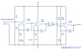
For a perfect op-amp the output of U1 would be at the same voltage as C3, and therefore the two inputs of U2 would both be at the same level, so it is random whether the output of U2 would be low or high.
However, a LM324 has a bias current of typically 10nA (maximum 60nA). That current establishes a voltage of 1mV across R3. The output of U1 (and the non-inverting input of U2) will therefore be 1mV higher than the inverting input of U2, so the output of U2 will go high.
To make things slightly more complicated, the LM324 has an offset voltage of ±600uV (maximum ±3mV). That adds a random element to the inputs of U2, so the output could be either high or low at rest, with a preference for high.
Would there be a chance of it working if the impedances were equal then? Of course, not counting with the offset voltage, because it could still go wrong because of it. But if the output was low at rest by chance, with equal impedances could it work?
Also, I didn't use that driver circuit, but thank you for the warning
If the impedances are equal, it would be truly random if it settled high or low in the absence an input. It is also likely to amplify random noise and interference and give an output signal when there is no input.
It would be better to bias the U2 input a little above 2.5V so that the output is definitely low for no input signal.
Also, with a 0.4V/us slew rate, an LM324 is not going to give anything that resembles a squarewave at 40kHz. It takes the whole half-cycle to slew from 0V to 5V, so the best you can hope for is a triangle.
 

Thread Starter

didifi

Joined May 8, 2023
31
If the impedances are equal, it would be truly random if it settled high or low in the absence an input. It is also likely to amplify random noise and interference and give an output signal when there is no input.
It would be better to bias the U2 input a little above 2.5V so that the output is definitely low for no input signal.
Also, with a 0.4V/us slew rate, an LM324 is not going to give anything that resembles a squarewave at 40kHz. It takes the whole half-cycle to slew from 0V to 5V, so the best you can hope for is a triangle.
I don't really mind the non-square wave at the output, since my goal is to have data to arduino when there is an ultrasound being received or not, so it's enough for me having 5V/0V to know when there is an ultrasound and when there isn't. Also, how would I bias the U2 input?
 

ericgibbs

Joined Jan 29, 2010
21,460
Hi did,
With that very basic program, it will oscillate, also on my test.
What do you want to happen when it's sensing the A1 input.??


E
 

Thread Starter

didifi

Joined May 8, 2023
31
Hi did,
With that very basic program, it will oscillate, also on my test.
What do you want to happen when it's sensing the A1 input.??


E
I wanted to have an Output signal on my ampOp that would have voltage (or higher voltage) when there is a signal, and a stable voltage when there is no input from the receiver. Since even when there is no signal from the receiver the output has a HIGH output, I thought when reading the A1 input, it would have a proportional number to the voltage on the ampOp output (which would be around 736 considering the output being 3.6V for example, since 5V - 1023, then 3.6x10²³/5 would give me around that number).
Then when the receiver is receiving an ultrasound, the voltage would be higher or the signal would oscillate. But I don't get it why it would oscillate while having a stable voltage in output (as it's shown in simulation when there is no input from the receiver it's just one stable line at 3.6V).
 

Ian0

Joined Aug 7, 2020
13,158
I don't really mind the non-square wave at the output, since my goal is to have data to arduino when there is an ultrasound being received or not, so it's enough for me having 5V/0V to know when there is an ultrasound and when there isn't. Also, how would I bias the U2 input?
It doesn't work like that. It's designed to give a 40kHz squarewave at the output when there is a signal. If you wanted a 5V output when there is a signal and a 0V output when there isn't, then you need a rectifier as well as the comparator.
As an alternative to the rectifier, if you correctly bias the output (post #21) then use the output from the comparator to trigger a retriggerable monostable (74HC123) you can have a true/false output to indicate the presence of a signal.
 

ericgibbs

Joined Jan 29, 2010
21,460
hi did,
With a fixed 3.6V on A1, this is what I see using your program, just a small fluctuation,+/- 5 counts.
Are you able to add some extra circuit to your project in order to see a steady pulse when a 40kHz signal is received.?
E
EG57_ 806.png
 

Thread Starter

didifi

Joined May 8, 2023
31
IT will, as I said in post #21. It's amplifying random noise on the input.
I see, I get it now. I tried another circuit with a diode but it didn't work as well. Is it because of the offset voltage and impedances as well? It was the same problem, the LED I used on the output was always ON. So maybe if I use a rectifier on the receiving circuit and adjust impedances/adapt the U2 input to be above 2.5V it could work?
 

Attachments

Thread Starter

didifi

Joined May 8, 2023
31
hi did,
With a fixed 3.6V on A1, this is what I see using your program, just a small fluctuation,+/- 5 counts.
Are you able to add some extra circuit to your project in order to see a steady pulse when a 40kHz signal is received.?
E
View attachment 293722
Hi, unfortunately this isn't what I get :/ when measuring voltage, I get 3.03V fixed on Vo (also sorry if I confused by saying output, I'm using Vo but I said output since it's an output, I forgot to differentiate the two). I get this oscillating sign from 1023 to 0 instead of a small fluctuaction. Maybe it's because in Vo I'm using a comparator? Where are you measuring A1? In output we don't have a comparator but in Vo we do, which I think it's the reason it's oscillating in extremes
1683547342723.png1683547151222.png
 

Thread Starter

didifi

Joined May 8, 2023
31
Hi, unfortunately this isn't what I get :/ when measuring voltage, I get 3.03V fixed on Vo (also sorry if I confused by saying output, I'm using Vo but I said output since it's an output, I forgot to differentiate the two). I get this oscillating sign from 1023 to 0 instead of a small fluctuaction. Maybe it's because in Vo I'm using a comparator? Where are you measuring A1? In output we don't have a comparator but in Vo we do, which I think it's the reason it's oscillating in extremes
View attachment 293725View attachment 293724
I tested it in Output as well and it gives me the same oscillation... instead of a small fluctuation
 

Ian0

Joined Aug 7, 2020
13,158
Take out R6 and replace it by 100k and 1k in series (100k to the V+ supply), and connect the non-inverting input of U2 to the junction of the 1k and 100k. That should make sure that the output is low when there is no signal, and give it a small threshold for signal detection below which it ignores the noise.
 

Thread Starter

didifi

Joined May 8, 2023
31
Hi,
It would be helpful if you explained exactly the purpose of the project.

E
I wanted to have a difference in Vo so I could differentiate when the receiver is receiving a wave and when it isn't. When it oscillates to extremes it makes it hard to know when it is actually receiving a wave, since it's always changing in between 0 and 5 V, even when there is no ultrasound. My purpose was to have different values in Vo, initially I wanted to have 0V when there is no signal and 5V when there is a signal, but even if that isn't possible I wanted to be able to differentiate it by voltage, for example. If Vo is fixed at 3V, then when the receiver receives an ultrasound, it should oscillate and therefore I wouldn't be receiving a stable signal anymore and would know the receiver has detected a wave. But when it oscillates between two extremes, I can't really tell when it's oscillating because it has detected an ultrasound.
 

Thread Starter

didifi

Joined May 8, 2023
31
Take out R6 and replace it by 100k and 1k in series (100k to the V+ supply), and connect the non-inverting input of U2 to the junction of the 1k and 100k. That should make sure that the output is low when there is no signal, and give it a small threshold for signal detection below which it ignores the noise.
I'm going to try that now thank you
 

Thread Starter

didifi

Joined May 8, 2023
31
Hi, I think I got it to work! now the Vo stays on only when the receiver is receiving. Although unfortunately the receiving distance is very little. Is it because when the receiver receives at a longer distance the voltage is lower than 2.5V therefore it doesn't count for the comparator? Also, was the connection like this?
1683628668082.png
 

Ian0

Joined Aug 7, 2020
13,158
Hi, I think I got it to work! now the Vo stays on only when the receiver is receiving. Although unfortunately the receiving distance is very little. Is it because when the receiver receives at a longer distance the voltage is lower than 2.5V therefore it doesn't count for the comparator? Also, was the connection like this?
View attachment 293801
You just need more gain.
Your circuit suggests that you should get a gain of 101, but look at the LM324’s open loop gain graph.
979CED41-C255-4FED-9FB6-95AF216A9195.pngIts open loop gain is only 25 at that frequency.
 

Thread Starter

didifi

Joined May 8, 2023
31
You just need more gain.
Your circuit suggests that you should get a gain of 101, but look at the LM324’s open loop gain graph.
View attachment 293802Its open loop gain is only 25 at that frequency.
Do you know other ampOps that would work better? I could use only analog data to arduino but I'm afraid that more gain will also mean it will amplify the noise higher and maybe get the comparator saturating positively when there's no sign... since in the last tests it amplified to 5V whenever there was noise.
 
Top