ultrasonic receiver circuit not working

Thread Starter

masterqueen93

Joined Mar 10, 2018
4
Hello,
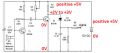
I am not very experienced with electronics but I wanted to make a ultrasonic transmitter and receiver circuit. I have a transmitter working with an arduino that generates a 40kHz signal and now I wanted to build a circuit for the receiver and. I used this circuit from https://www.pocketmagic.net/detecting-an-ultrasonic-beacon/.

When I build this circuit I get just a voltage around 4.5V at the signal pin, which should be between 0 and 5V. But if I move the transmitter further away the voltage doesn't change. Then I tried measuring before the diode, just the same(well the voltage is a bit higher) it doesn't change here either. Then I measured at the base of T2 and there is a signal on my scope, the voltage that it reads out is 0.44V at Vmax and the Vrms is 1.73V. this is also the same for when I measure at the base of T1 where signal comes in from the receiver, but here the voltage does change when I move the transmitter.
Does anyone know what I am doing wrong? The circuit should work as it shows on the website.
 

LesJones

Joined Jan 8, 2017
4,188
It is quite possible that you could have destroyed T2. If the potentiometer VR was turned to the point where the slider is at the base end of the track it would connect 5 volts straight across the bese emitter junction of T2 which would destroy it. I suggest that you add a resistor (Between 10K and 56K) between the bottom of the potentiometer and the base of T2 to limit the current to a safe value before you replace T2 to avoid destroying another transistor. Just because something is on a website does not mean it is correct.

Les.
 

Thread Starter

masterqueen93

Joined Mar 10, 2018
4
Thanks for your reply.
I did put a 560K resistor in stead of the potentiometer, should have mentioned it. I also replace the T2 but stil the same results.
 

AnalogKid

Joined Aug 1, 2013
11,036
The circuit is totally dependent on the adjustment of VR1. At 1 M ohm it is not supplying enough current to get T2 to the edge if its linear amplifier range. Adjust VR1 until there is about 2 V at the T2 collector, and try again.

To protect T2, add a resistor in series with VR1. Something around 47K to 100K.

ak
 

hobbyist

Joined Aug 10, 2008
892
VBT2 around 440mV. with 560K ohms in place of 1Meg, you are overdriving the base of the transistor , and the excessive current is dropping across the base resistor, causing base voltage drop this in turn is cutting the transistor off, more or less its a base emitter diode in series taking all the current.

Keeping the fixed 560K resistor in place, add a 500K pot, to this branch, then adjust it till you get around 2 to 3 volts at the T2 collector.

Around 960K ohms would put the collector close to 2 -1/2 volts or so. depending on the component variations.
 
Last edited:

AnalogKid

Joined Aug 1, 2013
11,036
Around 960K ohms would put the collector close to 2 -1/2 volts or so. depending on the component variations.
Given that you don't know the Vbe nor the gain of the transistor he is using (not the values on the datasheet, but the those of the individual part in his hand) nor the temperature in the room, I'm curious about how you arrived at that value.

ak
 

Thread Starter

masterqueen93

Joined Mar 10, 2018
4
So I have been trying your suggestions. I couldn't find any pots(dont know where they went). So I just tried it with some different resistors and have the collecter now between 2 and 3 volts, but still no different. On the emitter sides it still reads out 5V but with no changes, the signal still comes in at the base.
Does anyone maybe know a different circuit for this, I found some with the use of op-amps but I dont have them so couldnt try that out. If anyone know something with just some simle components I would be very happy.
 

hobbyist

Joined Aug 10, 2008
892
Given that you don't know the Vbe nor the gain of the transistor he is using (not the values on the datasheet, but the those of the individual part in his hand) nor the temperature in the room, I'm curious about how you arrived at that value.

ak
I thought the collector resistor was 5.6K ohms, but with a magnifying glass it shows 6.8K ohms, so it wont be in the 960K ohm range, (whoops), but rather around the 1 Meg to 1.3 Meg range.
 

ebp

Joined Feb 8, 2018
2,332
The transistor used has a current gain in the range of 110 to 800, so predicting the base current required to centre the collector at about half of supply is pretty much not possible. It would be somewhere between about [EDIT: fixed values, used wrong collector current before] 0.5.µA and 3.4 µA.
- collector current with collector at 2.5 V (2.5 V across 6.8 k) = 2.5/6800 = 368 µA
- divided collector current by current gain limits to estimate base current, so 368/800 and 368/110 for the approximate lower and upper values, respectively


If you have the circuit on a breadboard, here is a simple test to confirm the transistor is OK:
- remove C2
- set VR to anything in the range of 5k to 50k, or use a fixed resistor in that range
- power up and check the voltage at the collector of T2 - it should be nearly zero
- short the base of T2 to circuit common (ground); the voltage at the collector should now be equal to the supply voltage (nominally 5 V)

If you don't get these results the transistor is dead.
 
Last edited:

Audioguru

Joined Dec 20, 2007
11,248
How can the emitter be 5V when it is connected to the negative wire of the power supply so it is 0V?
Maybe your power supply is backwards?

The collector of T1 should also be +2V to +3V.
Connect and measure it like this:
 

Attachments

Thread Starter

masterqueen93

Joined Mar 10, 2018
4
Uhm... I feel really really stupid to have to admit this but as I was trying to measure the voltages as sugested by @Audioguru I found out that i placed my second NPN backwards... I check the circuit at least a million times but I missed that..
It workes now, I put a 560K resistor before the base so that the collecter has a bit more than 2V.
I want to thank you all for helping me.
 
Top