Ultrasonic Power Supply Output Signal Question

Thread Starter

amspurge

Joined Jan 15, 2016
50
Hello,

I am analyzing the output signal of an ultrasonic power supply that is typically used for welding plastic.

I am trying to compare two different power supplies to understand how the output changes when loaded vs. unloaded.

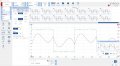
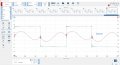
In the images attached, the blue shows the voltage at the output and red is the amperage. The amperage is measured with a resistor in series on the output.

My question is, why is there such a strange waveform for the current? This is running at 40kHz.

Image 93 (Board A) has a much cleaner waveform than 94 (Board B). Any idea why this would occur?
 

Attachments

Shadow123

Joined Jul 25, 2024
14
The difference in the current waveform (especially on Board B with the distorted current waveform) can be due to:

Load Characteristics:
When loaded, ultrasonic power supplies can experience non-ideal interactions with the transducer and the material being welded. This could result in complex impedance, which in turn affects the current waveform.

If Board B is driving a different type of transducer or load compared to Board A, or if the load on Board B is more reactive (capacitive or inductive), this could cause distortion in the current waveform.

Power Supply Design Differences:
If Board B uses a different circuit topology or power components (like different MOSFETs, drivers, or transformers), it may result in a less efficient or noisier power output, leading to current waveform irregularities.

For example, improper filtering or control loop design could allow harmonics or switching noise to affect the current.

Series Resistor:
If the series resistor used to measure the current is different between the two boards, it could introduce distortion into the current measurement. A higher-value resistor could increase noise or affect the accuracy of your measurement at 40 kHz.

Control and Feedback System:
Many ultrasonic power supplies use a feedback loop to regulate output power. If Board B has a less precise feedback loop or one that reacts slower to load changes, this could result in irregular current waveforms.

A mismatch between the phase of the voltage and current signals due to improper control could also explain why Board B has a distorted current signal.

Switching Artifacts:
At 40 kHz, power supplies rely on fast switching components (such as MOSFETs or IGBTs). If Board B’s components are switching less cleanly (e.g., due to slower rise times or improper gate drive), this could result in higher harmonic content in the current, distorting the waveform.

Transformer Saturation:
If Board B’s output transformer is being pushed toward saturation, especially when under load, it could cause non-linearities in the current waveform. Transformer saturation distorts the current by causing the waveform to flatten or become jagged.

Troubleshooting Suggestions:

Look for differences in the power components (transistors, transformers, or control ICs) between Board A and B.
Use a spectrum analyzer or FFT function on your oscilloscope to check for harmonics in the current waveform on Board B.
Ensure that both boards are driving the same load and that the load behaves similarly under both power supplies.
Make sure the resistor values and their placement are consistent between both boards to avoid measurement-induced distortion.
 

Thread Starter

amspurge

Joined Jan 15, 2016
50
The difference in the current waveform (especially on Board B with the distorted current waveform) can be due to:

Load Characteristics:
When loaded, ultrasonic power supplies can experience non-ideal interactions with the transducer and the material being welded. This could result in complex impedance, which in turn affects the current waveform.

If Board B is driving a different type of transducer or load compared to Board A, or if the load on Board B is more reactive (capacitive or inductive), this could cause distortion in the current waveform.

Power Supply Design Differences:
If Board B uses a different circuit topology or power components (like different MOSFETs, drivers, or transformers), it may result in a less efficient or noisier power output, leading to current waveform irregularities.

For example, improper filtering or control loop design could allow harmonics or switching noise to affect the current.

Series Resistor:
If the series resistor used to measure the current is different between the two boards, it could introduce distortion into the current measurement. A higher-value resistor could increase noise or affect the accuracy of your measurement at 40 kHz.

Control and Feedback System:
Many ultrasonic power supplies use a feedback loop to regulate output power. If Board B has a less precise feedback loop or one that reacts slower to load changes, this could result in irregular current waveforms.

A mismatch between the phase of the voltage and current signals due to improper control could also explain why Board B has a distorted current signal.

Switching Artifacts:
At 40 kHz, power supplies rely on fast switching components (such as MOSFETs or IGBTs). If Board B’s components are switching less cleanly (e.g., due to slower rise times or improper gate drive), this could result in higher harmonic content in the current, distorting the waveform.

Transformer Saturation:
If Board B’s output transformer is being pushed toward saturation, especially when under load, it could cause non-linearities in the current waveform. Transformer saturation distorts the current by causing the waveform to flatten or become jagged.

Troubleshooting Suggestions:

Look for differences in the power components (transistors, transformers, or control ICs) between Board A and B.
Use a spectrum analyzer or FFT function on your oscilloscope to check for harmonics in the current waveform on Board B.
Ensure that both boards are driving the same load and that the load behaves similarly under both power supplies.
Make sure the resistor values and their placement are consistent between both boards to avoid measurement-induced distortion.
Wow! Thank you for the detailed answer. Both boards are driving the same transducer and the both have the same transformer. The series resistor was the same for both tests as well. The H-bridges are completely different, however. I’ll look into the specs of each and see where I might find differences. There is some know impedance mismatch between the load and source on board B that was found, so that may also be paying a role.

Another big difference is the frequency tracking method. Board A uses a PLL, while Board B uses a microcontroller to track phase. I’m assuming that the analog nature of the PLL can provide much better resolution, but does this even play a role in the distortion? As I’m writing this I’m realizing it likely comes from something in the switching of the mosfets.
 

MisterBill2

Joined Jan 23, 2018
27,164
What I think I see is that the power supply feeding the H-bridge is mostly AC, and the H bridge is reversing the polarity. So you have both AC and a switch with the H-bridge reversing the polarity
 
Top