Two Load Cells giving different readings all the time

Thread Starter

Ashane

Joined Aug 19, 2017
24
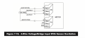
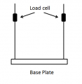
I am currently doing a project which utilizes two load cells. A pseudo 2-D rectangular box (800 mm*600 mm*100 mm) is suspended by two load cells (LCM-101-100 from OMEGA) at the two ends along the 800 mm length. The two load cells are connected to DP41-B panel meters respectively. The 2-D box will be filled up with 80 kg of aggreagates maximum. However, I need to calibrate the two load cells with the panel meter readings. Therefore, a base plate is attached below the 2-D box and the calibration is done without the 2-D box. But when I keep a 5kg disc (any mass) along this base plate every time I get a different reading from both the load cells. I want this reading to be a constant reading for a specific mass (no matter where I keep the mass along the base plate). I need to find a way to detect that there is only 5kg on top of the base plate in whatever the orientation or where ever it is at. Any suggestions?

The load cell output is 30 mV/V (maximum for 100 kg). I am using the bridge configuration (an option in the panel meter). Please ask me if any grey areas. Your help is much appreciated.
 

Attachments

ericgibbs

Joined Jan 29, 2010
21,390
hi Ashane.
How are the two load cells wired/connected to the amplifier/indicator.?
Do you have a sketch to post.?
E
EDIT:
On a load sharing arrangement with load cells it is usual to connect the load cells in parallel.
 

Thread Starter

Ashane

Joined Aug 19, 2017
24
Thank you for the reply E.

I have adjusted the jumper settings inside the panel meter and I have connected the wires to the panel meter in a specific way (attached from the DP41-B manual). The panel meter provides an internal excitation. Both the load cells are connected to the panel meters (two) in the same way. Screen Shot 2017-08-19 at 2.58.48 PM.png
 

Attachments

WBahn

Joined Mar 31, 2012
32,702
Do a static analysis of the load seen by each cell -- you will see that the load on each varies as the center of gravity of the load moves across the beam.

What you need to do is totalize the two measurements (i.e., add them together).
 

ericgibbs

Joined Jan 29, 2010
21,390
hi,
When using two load cells with their own indicators, you will get a different weight value on the meters depending upon the position of the load relative to the two meters.
[ btw this is the method used for measuring individual axle weight loading on vehicles]

Is it possible to try using only one meter to drive both load cells wired in parallel.?
By being in parallel you will get a sum value of the two cells, were ever the load is positioned.

E
 

Thread Starter

Ashane

Joined Aug 19, 2017
24
Do a static analysis of the load seen by each cell -- you will see that the load on each varies as the center of gravity of the load moves across the beam.

What you need to do is totalize the two measurements (i.e., add them together).

Hi WBahn, thank you for your reply. I tried this.
But if I put 5kg at one end, that load cell with have the calibrated value (for the 5kg) plus the loadcell at the other end will also show a value. If I add both of them up, then it will be above 5 kg. :(
 

Thread Starter

Ashane

Joined Aug 19, 2017
24
hi,
When using two load cells with their own indicators, you will get a different weight value on the meters depending upon the position of the load relative to the two meters.
[ btw this is the method used for measuring individual axle weight loading on vehicles]

Is it possible to try using only one meter to drive both load cells wired in parallel.?
By being in parallel you will get a sum value of the two cells, were ever the load is positioned.

E
Hi E, I can try doing this. Afterwards, if I want to calibrate it, I can keep the weight anywhere and calibrate? or should it be in the middle?
 

WBahn

Joined Mar 31, 2012
32,702
Hi WBahn, thank you for your reply. I tried this.
But if I put 5kg at one end, that load cell with have the calibrated value (for the 5kg) plus the loadcell at the other end will also show a value. If I add both of them up, then it will be above 5 kg. :(

Where is the calibrated value coming from? I thought that's what you were trying to do -- calibrate the system.

I don't know what your setup is, exactly, but I assume you have the load cells zeroed when just the beam is attached and empty.

Now put your 5 kg weight in the middle of the beam, as close to centered as you can get it. Adjust the system so that each cell reads 2.5 kg. Now remove the weight and, if necessary, rezero the meters. Keep repeating this until you get two 0 kg readings with the beam empty and two 2.5 kg readings with the 5 kg weight right in the middle. Now as you move the weight around on the beam the sum of the readings should be pretty close to 5 kg. If they aren't, then something else is going on.
 

ericgibbs

Joined Jan 29, 2010
21,390
'Ideally' you should be able to place the weight anywhere on the base. but I have found that with a base that has four load cells, one at each corner, they can give very small differences in weight depending where the weight is placed.
This is partly due to the base/platform construction, you may see a small difference in weight/position.
BTW: I am assuming paralled L/C's.
E
 

WBahn

Joined Mar 31, 2012
32,702
hi,
When using two load cells with their own indicators, you will get a different weight value on the meters depending upon the position of the load relative to the two meters.
[ btw this is the method used for measuring individual axle weight loading on vehicles]

Is it possible to try using only one meter to drive both load cells wired in parallel.?
By being in parallel you will get a sum value of the two cells, were ever the load is positioned.

E
But I think each cell has to be individually calibrated first, doesn't it? If either has an offset or gain error, then that will be reflected in the paralleled measurement.
 

ericgibbs

Joined Jan 29, 2010
21,390
But I think each cell has to be individually calibrated first, doesn't it. If either has an offset or gain error, then that will be reflected in the paralleled measurement
If it is a system that needs to be accurate a 'summing' PCB is used to connect the cells to a common point.
The potentiometers on the PCB set the Excitation voltages for each L/C and the Span/Zero, most general purpose scales do not have the PCB, just a direct parallel connection.


EDIT:
Attached a PDF for L/C's. it may help the OP. Pages #45/46
 

Attachments

WBahn

Joined Mar 31, 2012
32,702
If it is a system that needs to be accurate a 'summing' PCB is used to connect the cells to a common point.
The potentiometers on the PCB set the Excitation voltages for each L/C and the Span/Zero, most general purpose scales do not have the PCB, just a direct parallel connection.


EDIT:
Attached a PDF for L/C's. it may help the OP. Pages #45/46
So I'm gathering that putting them in parallel assumes that the load cells are essentially hard-calibrated for offset/gain and that any residual errors are simply tolerable. I'm also assuming that for this to work the load cells have to be essentially identical.

I've never worked with a system that had multiple load cells. All of my work has involved single, high-grade measurements (ounce-scale resolution at 10,000 lb type stuff) so I was worried about stuff at the other end of the spectrum.
 

ericgibbs

Joined Jan 29, 2010
21,390
hi WB
The load cells 'sets' are ordered to be 'identical', most manufacturers will calibrate/match the load cells and supply with a calibration specification, if requested.

I have manufactured a large number of weighing projects/products over the years and I would only use a summing PCB at the clients request.
If you fit a summing PCB, some on site technician is bound to fiddle with it and throw out the calibration.

The range of weighing projects I have covered since retiring, range from 30kg thru 2000kg, weighing animal feed and animals.
We have a farm in South Africa, so I get all the' can you do this or that' jobs, prior to that very heavy weighing in the steel industry.

E
 

Thread Starter

Ashane

Joined Aug 19, 2017
24
Where is the calibrated value coming from? I thought that's what you were trying to do -- calibrate the system.

I don't know what your setup is, exactly, but I assume you have the load cells zeroed when just the beam is attached and empty.

Now put your 5 kg weight in the middle of the beam, as close to centered as you can get it. Adjust the system so that each cell reads 2.5 kg. Now remove the weight and, if necessary, rezero the meters. Keep repeating this until you get two 0 kg readings with the beam empty and two 2.5 kg readings with the 5 kg weight right in the middle. Now as you move the weight around on the beam the sum of the readings should be pretty close to 5 kg. If they aren't, then something else is going on.
WBahn, the calibrated values are coming from previously calibrated curves (individually). Trying to calibrate the combined system
 

Thread Starter

Ashane

Joined Aug 19, 2017
24
hi WB
The load cells 'sets' are ordered to be 'identical', most manufacturers will calibrate/match the load cells and supply with a calibration specification, if requested.

I have manufactured a large number of weighing projects/products over the years and I would only use a summing PCB at the clients request.
If you fit a summing PCB, some on site technician is bound to fiddle with it and throw out the calibration.

The range of weighing projects I have covered since retiring, range from 30kg thru 2000kg, weighing animal feed and animals.
We have a farm in South Africa, so I get all the' can you do this or that' jobs, prior to that very heavy weighing in the steel industry.

E

Hi E,

I bought 2 load cells which are of the same model (LCM101-100). I hope both of them are identical. because in both the cells the output for the maximum load (i.e. 100 kg) is 30 mV.
 

ericgibbs

Joined Jan 29, 2010
21,390
hi A,
Have you had the opportunity to carry out a calibration and load displacement check, with both L/C's are connected in parallel to one indicator unit.?
Please let us know what you measure.
E
 

Reloadron

Joined Jan 15, 2015
7,855
The DP41 is an excellent meter as are the Omega Load Cells. That said you can't use the 3mV/volt (30 mV Full Scale) as a calibration. That is an approximate number. I suggest you hang a known weight on each load cell and additionally measure the excitation voltage from the DP14 as it is adjustable. Two load cells will not have identical mV/volt outputs, they will be close but not the same and thus the need for a known weight placed on each cell. Then with no weight calibrate the DP 41 in accordance with manufacturers instruction and then place a weight close to 90% or so of full scale and again calibrate. This amounts to placing zero weight on the cell and telling the DP 41 Read Zero, then with close to full scale Read whatever the actual weight is. Using the DP41 and not having a known weight will not work for you. Over the years I literally used dozens of those meters so I have been there and done that with the DP41. Once you do this the meters should agree or be within a few counts.

Ron
 

Thread Starter

Ashane

Joined Aug 19, 2017
24
hi A,
Have you had the opportunity to carry out a calibration and load displacement check, with both L/C's are connected in parallel to one indicator unit.?
Please let us know what you measure.
E
Hi E, I will try this within the next two days (excluding Sunday) and will reply you on the thread.
 

Thread Starter

Ashane

Joined Aug 19, 2017
24
The DP41 is an excellent meter as are the Omega Load Cells. That said you can't use the 3mV/volt (30 mV Full Scale) as a calibration. That is an approximate number. I suggest you hang a known weight on each load cell and additionally measure the excitation voltage from the DP14 as it is adjustable. Two load cells will not have identical mV/volt outputs, they will be close but not the same and thus the need for a known weight placed on each cell. Then with no weight calibrate the DP 41 in accordance with manufacturers instruction and then place a weight close to 90% or so of full scale and again calibrate. This amounts to placing zero weight on the cell and telling the DP 41 Read Zero, then with close to full scale Read whatever the actual weight is. Using the DP41 and not having a known weight will not work for you. Over the years I literally used dozens of those meters so I have been there and done that with the DP41. Once you do this the meters should agree or be within a few counts.

Ron
Ron, your reply is much appreciated. You are absolutely correct regarding the different voltages. Two load cells have 29.968 mV and 30.002 mV on full scale readings.
So what you want me to do is, RDG.CNF>RD.SC.OF>Enable>2C D.int>ONLINE and put the two weights in and calibrate the two load cells separately?
And afterwards, will I be able to use these two loadcells in my connected system?
 
Top