Facebook
 Google
 GitHub
 Linkedin
Hello everyone...
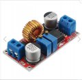
I'm using a 4S 18650 battery pack and its BMS board in one of my project. I'm using a constant voltage buck boost converter to boost the voltage from 12v to 18v and then using a CC/CV buck converter to buck the voltage to the required voltage of 16.8 for the battery pack. The reason I'm using two of these modules is to due to the lack of availability of an appropriate CC/CV buck boost converter. Anyhow the thing works fine since i have tested it with led strips and works as expected.
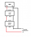
The problem starts when i hook the output of the CC/CV buck module to the P- of the BMS (battery management system) Since the ground terminal is common for the P- and CC/CV buck converter input (output ground of CV buck boost converter) and output. So its clear that the resistance for the constant current function is bypassed and thus the constant current function doesn't work and its also mentioned in the circuit board discription that the input and output ground should not be shorted for the board to work properly.
So what I'm looking for is a solution to separate these two grounds from each other. What might be the possible solution.. apart from replacing the entire modules since the project is almost completed and all wiring has been done.
any help would be appreciated...
I'm using a 4S 18650 battery pack and its BMS board in one of my project. I'm using a constant voltage buck boost converter to boost the voltage from 12v to 18v and then using a CC/CV buck converter to buck the voltage to the required voltage of 16.8 for the battery pack. The reason I'm using two of these modules is to due to the lack of availability of an appropriate CC/CV buck boost converter. Anyhow the thing works fine since i have tested it with led strips and works as expected.
The problem starts when i hook the output of the CC/CV buck module to the P- of the BMS (battery management system) Since the ground terminal is common for the P- and CC/CV buck converter input (output ground of CV buck boost converter) and output. So its clear that the resistance for the constant current function is bypassed and thus the constant current function doesn't work and its also mentioned in the circuit board discription that the input and output ground should not be shorted for the board to work properly.
So what I'm looking for is a solution to separate these two grounds from each other. What might be the possible solution.. apart from replacing the entire modules since the project is almost completed and all wiring has been done.
any help would be appreciated...