 Facebook
 Google
 GitHub
 Linkedin
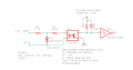
I want to protect the inputs of my PC847 opto-isolator, which operates between a voltage of 3V up to 24V, from ESD events and extratension. My idea was to do something similar to the circuit I found on the web, but using an SMBC30CA as a TVS diode.
Now I have doubts. The resistor R3 is supposed to limit the discharge current of the ESD event, in some diagrams I find only the TVS diode without any current limitation, but in doing so the circuit that is inserted at the input would short-circuit if the voltage exceeds the breakdown voltage of the TVS diode. On the other hand, resistor R3, I believe, lowers the effective protection of the TVS diode. In other circuits I find instead of resistor R3 a resettable fuse, which would be a good idea, but I don't know how to size the two components.
Can anyone help me?
Attachments
-
 13 KB Views: 47


