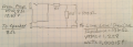
The goal is for the output impedance of the attenuator network (basically R1 and R2 in parallel) to be so much less than the 10 K input impedance that the output voltage does not change (much) when the output is connected to the device. The engineering rule of thumb is for the two to be at least 10:1 - for a 10 K load you want the source impedance to be less than 1 K. Not a problem in your case, so let's go to 100:1. Fix R2 at 100 ohms, and calculate R1 for the desired attenuation. Whatever R1 is, it will lower the output impedance even more, not a bad thing.
Can you get back to the engineers with this question: "What is the value of "line level" that they design to?" An answer in dB doesn't tell us much because a dB is a ratio, and without knowing which standard or reference value they use, we cannot calculate anything. We prefer an answer in volts RMS, volts peak, or volts peak-to-peak.
The device plugged into the "line level" jack is designed to be used with an amplifier such as this, but it is normally placed before the input instead of after the output (as I am endeavoring to use it). Shouldn't the grounds for both devices (and their mutual compatibility) be the same potential either way it is connected?
Basically you’re building a speaker level direct box. I’ve experienced ground issues when coupling amps. Sometimes it’s a shock other times noise. Many designs include a ground lift.
Basically you’re building a speaker level direct box. I’ve experienced ground issues when coupling amps. Sometimes it’s a shock other times noise. Many designs include a ground lift.
The goal is for the output impedance of the attenuator network (basically R1 and R2 in parallel) to be so much less than the 10 K input impedance that the output voltage does not change (much) when the output is connected to the device. The engineering rule of thumb is for the two to be at least 10:1 - for a 10 K load you want the source impedance to be less than 1 K. Not a problem in your case, so let's go to 100:1. Fix R2 at 100 ohms, and calculate R1 for the desired attenuation. Whatever R1 is, it will lower the output impedance even more, not a bad thing. Now comes the fun part - there are several definitions of "line level": https://en.wikipedia.org/wiki/Line_level Can you get back to the engineers with this question: "What is the value of "line level" that they design to?" An answer in dB doesn't tell us much because a dB is a ratio, and without knowing which standard or reference value they use, we cannot calculate anything. We prefer an answer in volts RMS, volts peak, or volts peak-to-peak. ak
Back of the napkin, the resistor values look OK. Most of the voltage will be dropped across the 930 ohm resistor, let's assume all of it is. P = E²/R. For the 930 ohm and an voltage of 12.65 RMS, we get a power dissipation of 12.65²/R = 0.172 watts. I'd use a 1/2 watt resistor, although a 1/4 would do. The 100 ohm will dissipate much less power, 1/4 or even 1/8 watt would be sufficient.
If you turn the amp down, the voltage at your output point will go down.
Would R1 = 93 ohms and R2 = 10 ohms (basically 1/10th of the previous numbers) work just as well? - while affecting the line-level signal, and possibly "tone", less?
I'm trying to match a line-level device with impedance = 10k ohms, and VRMS = 1.228. If I turn my amp down to use 15 watts (out of the full 20 watts) of my amp, would I still be able to use the device? Or should I measure the amp's output after I set the amp's volume control where I want it, then re-do all the math/resistors to match?
I wouldn't go any lower on the resistor values You could probably increase them by a factor of 2 or 4 and still not have any loading problem.
Yes, the level will go down when you turn down the amplifier, and it might be best to recalculate the resistor values at the nominal listening level. But 'line level' is generally poorly defined and can vary quite a bit (I've seen 'line level' defined as anything between 0.5 and 2 volts peak).
It’s true but assuming pro audio line level is +4dBu. Just start low and back off if it starts to clip. Most pro audio line level is also balanced but it should be fine.
I wouldn't go any lower on the resistor values You could probably increase them by a factor of 2 or 4 and still not have any loading problem.
Yes, the level will go down when you turn down the amplifier, and it might be best to recalculate the resistor values at the nominal listening level. But 'line level' is generally poorly defined and can vary quite a bit (I've seen 'line level' defined as anything between 0.5 and 2 volts peak).
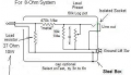
Thanks again for your help, Ylli. Wolframore suggested a ground lift switch. That's just a break in the ground path with a simple switch, right? Where do you think would be the best place to put it? Just before the line-out jack's "sleeve"?
It’s true but assuming pro audio line level is +4dBu. Just start low and back off if it starts to clip. Most pro audio line level is also balanced but it should be fine.
Oh, there you are! I'll just ask you... You suggested a ground lift switch. That's just a break in the ground path with a simple switch, right? Where do you think would be the best place to put it? Just before the line-out jack's "sleeve"?
By "start low and back off if it starts to clip", you mean start with resistors of R1 = 93 ohms and R2 = 10 ohms? And how do I know when it clips?
Can’t do it with an L-pad design. For ground lift you need isolation. I tried to bring this up early on. L-pads are better for +4 to 0 dBu drop for mic vs line input
Can’t do it with an L-pad design. For ground lift you need isolation. I tried to bring this up early on. L-pads are better for +4 to 0 dBu drop for mic vs line input
Gotcha, not a problem, my line-level device does have a ground lift (I checked) so I'll just use that if necessary.
When you said "start low and back off if it starts to clip", did you mean start with resistors of R1 = 93 ohms and R2 = 10 ohms? And how do I know when it clips?
Nooooo!!!.... you need to learn to use Ohm's law and calculate the current... it's V=I*R... do the power calculation... your resistors would have to be massive to do 100 ohms total resistance on the L-Pad... remember you have 20 watts coming out...
Start with your 10k : 1K divider and watch our amp level... start low and pull back if you get clipping.
Can’t do it with an L-pad design. For ground lift you need isolation. I tried to bring this up early on. L-pads are better for +4 to 0 dBu drop for mic vs line input

 Facebook
 Google
 GitHub
 Linkedin