 Facebook
 Google
 GitHub
 Linkedin
Hi all,
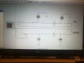
Could anyone help me with this? "investigate the input and output values and thresholds for CMOS and TTL logic devices use appropriate lab equipment and Proteus simulations to perform tests using the CMOS HCF4069 and TTL74ls04 IC’s
Gradually increase the input voltage from 0v to 5v and note readings at 100mV intervals on the output."
I have it build in Proteus, however it is not working correctly . Can anyone advise how to make it working?
Picture attached
Thanks
Could anyone help me with this? "investigate the input and output values and thresholds for CMOS and TTL logic devices use appropriate lab equipment and Proteus simulations to perform tests using the CMOS HCF4069 and TTL74ls04 IC’s
Gradually increase the input voltage from 0v to 5v and note readings at 100mV intervals on the output."
I have it build in Proteus, however it is not working correctly
. Can anyone advise how to make it working? Picture attached
Thanks
Attachments
-
 165.1 KB Views: 22


