
I have a Whites Coinmaster 6000/Di Series 2 that turns on but has no sound and the meter won't register past half way, unless in battery test mode. It did not work at all when I got it. Took it apart and found a burnt connection from the positive bettery terminal to the Off/VDI Level/Battery Check potentiometer. Replaced the connection on the board now here I am. Any information or schematics about this would be appreciated.
Trying to revive an old metal detector
- Thread starter justinberry
- Start date
Scroll to continue with content
Wolframore
- Joined Jan 21, 2019
- 2,610
take pictures!
Four black ones two grey. I'm circuit learning so bear with me. I have the schematics for the 5000 (file added) detector but as I've learned doesn't help me any. I couldn't find one for the 6000 series 2. Working on photos of the board.
Attachments
-
172.2 KB Views: 58
.jpg")
.jpg")
.jpg")
.jpg")
.jpg")
Thank you guys
I searched and searched and found one at geotech. Thank you!You can check geotech1.com forum. Lots of schematics of metal detectors. With so little information I can't help.
... Looking at the schematic that you have posted, the operational amplifiers are shown to have a positive voltage supply, labeled VCC. In the 5000 model schematic, VCC is labeled as 9.0 volts. Are you able to verify that the op-amp voltage supply on your board is working as it should be? This would require looking up the pin-out of one of the op-amps and trying to measure the VCC pin with respect to ground. This is not particularly simple, since there do not seem to be any clear labels or component markings in the pictures.
... Let me re-word that last post. There should be two 8 pin integrated circuit chips on your circuit board someplace. I am guessing it is 8 pins, anyway. Each chip will have 2 op-amps as well as a positive voltage pin and a ground pin on each chip. The positive voltage pin needs to be measured with a voltmeter to be sure that the op-amps can work correctly.
... Can you locate the 8 pin op-amp chips? The number may be RC 4558 or LM 358, or could be something different since you have the 6000 version.
... I see that there is also an 8 pin CA3130 op-amp someplace on the 5000 version.
... This is an educated guess at this point. The idea is to locate the op-amp chips, if they are there someplace. If even one of these op-amp chips can be located on the circuit board, then it should be possible to verify that the VCC supply is working correctly.
Last edited:
No sir, on my 6000 there are no board markings other than the circuit numbers for reference in the schematics. But, I think I've found the schematics for the 6000 (finally) so I will check into this. The 5000 I figured would be close to the 6000 circuitry but it's not. 5000 battery pack consist of (1) 9V and (4) AA for power and the 6000 I have only takes a battery pack consisting of (4) C batteries. Thank you... Looking at the schematic that you have posted, the operational amplifiers are shown to have a positive voltage supply, labeled VCC. In the 5000 model schematic, VCC is labeled as 9.0 volts. Are you able to verify that the op-amp voltage supply on your board is working as it should be? This would require looking up the pin-out of one of the op-amps and trying to measure the VCC pin with respect to ground. This is not particularly simple, since there do not seem to be any clear labels or component markings in the pictures.
... The main thing is to locate one of the op-amp chips and then look up which pin is the voltage supply ... maybe the supply pin for that chip will be shown as V+ or something like that. Then with one meter probe on circuit ground (the chip ground pin should also be ok here) and the other on that V+ pin, and the meter set to measure DC volts, confirm that a nominal voltage is present on V+. ... Can't say for sure what that voltage will be ... it likely has to go through a regulator circuit ... which could be a place for it to be something different from the battery voltage. However, even after it passes through the voltage conditioner circuit, it will still be something that makes sense, not zero or near zero.
I counted 7 total on both boards. 4 of them are on the main board and are as follows: LM358, LM393, RC4193DE, NE5534P. I already replaced the LM358 because the pins where charred. I've also replaced a 6520 transistor and a 63v 4.7uf electrolytic capacitor. All were around the audio area. When I first got it it didn't work and found that f1(fuse) on the board was fried through so I replaced it with one I found on an old electronic board and got the detector to power on. All of those wire fuses are the same aren't they. The one I put in isn't restricting current or anything is it? If you need me to circle the op amps on the photos I provided let me know.... Let me re-word that last post. There should be two 8 pin integrated circuit chips on your circuit board someplace. I am guessing it is 8 pins, anyway. Each chip will have 2 op-amps as well as a positive voltage pin and a ground pin on each chip. The positive voltage pin needs to be measured with a voltmeter to be sure that the op-amps can work correctly.
... Can you locate the 8 pin op-amp chips? The number may be RC 4558 or LM 358, or could be something different since you have the 6000 version.
... I see that there is also an 8 pin CA3130 op-amp someplace on the 5000 version.
... This is an educated guess at this point. The idea is to locate the op-amp chips, if they are there someplace. If even one of these op-amp chips can be located on the circuit board, then it should be possible to verify that the VCC supply is working correctly.
I ordered new leads for my multimeter just for this occasion awhile back. Haven't used them yet though... The main thing is to locate one of the op-amp chips and then look up which pin is the voltage supply ... maybe the supply pin will be shown as V+ or something like that. Then with one meter probe on circuit ground (the chip ground pin should also be ok here) and the other on that V+, and the meter set to measure DC volts, confirm that a nominal voltage is present on V+. ... Can't say for sure what that voltage will be ... it likely has to go through a regulator circuit ... which could be a place for it to be something different from the battery voltage. However, even after it passes through the voltage conditioner circuit, it will still be something that makes sense, not zero or near zero.
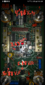
I circled and labled the four on the main board. The one in red is the one I changed and the other three yellow are the others.
Attachments
-
 1.4 MB Views: 19
I tested the four op-amp chips on the main board. The battery's input is 6V. On the attachment I have noted each chips Volts. Should I test the other three chips on the board that's connected to the main board? As this would be a bit of a challenge the way I have everything hooked up to where I could get to the main board. Going to bed now, racked my brain enough for one day but excited about the progress.
Voltage for main board op-amp chips.
Attachments
-
 1.4 MB Views: 20
... ok ... just to be clear ... you have located pin #7 on the NE5534 op-amp, and it measures 4.86 volts DC? The pins are numbered, with the dimple dot on the left, 1, 2, 3, 4 from left to right, going across the bottom, and then going from right to left across the top 5, 6, 7, 8. ... |If that's not clear then download the data sheet pdf for the NE5534 which will have an image to look at.
... Your measurement of 4.86 volts as the supply voltage for the NE5534 is below the minimum voltage given in the datasheet necessary for the op-amp to operate. It needs to be at least 5 volts DC.
... So there may be a problem if there isn't at least 5 volts present on that op-amp. If you know your batteries are good, clean the battery contact clips, and also the battery ends with fine grade emery cloth and electrical contact cleaner spray, then put the batteries back in, and see if you can get 5 volts across the NE5534 supply pins.
... There is one more possible component to look at as far as reaching the minimum op-amp voltage ... a zener diode. However, locating it on the circuit board in order to check it may not be simple.
Last edited:
I'm sorry, I read it like a 358. The voltage on NE5534 #7 IS 4.92. that's using pin 4 as ground. Should it be on or above 5 volts?... ok ... just to be clear ... you have located pin #7 on the NE5534 op-amp, and it measures 4.86 volts DC? The pins are numbered, with the dimple dot on the left, 1, 2, 3, 4 from left to right, going across the bottom, and then going from right to left across the top 5, 6, 7, 8. ... |If that's not clear then download the data sheet pdf for the NE5534 which will have an image to look at.
... Your measurement of 4.86 volts as the supply voltage for the NE5534 is below the minimum voltage given in the datasheet necessary for the op-amp to operate. It needs to be at least 5 volts DC.
... So there may be a problem if there isn't at least 5 volts present on that op-amp. If you know your batteries are good, clean the battery contact clips, and also the battery ends with fine grade emery cloth and electrical contact cleaner spray, then put the batteries back in, and see if you can get 5 volts across the NE5534 supply pins.
... There is one more possible component to look at as far as reaching the minimum op-amp voltage ... a zener diode. However, locating it on the circuit board in order to check it may not be simple.
Ok. Just checked NE5534 again but this time used the negative battery terminal on the board as ground instead of the op-amps VCC- pin and got 5.40 volts so maybe a grounding issue?
You May Also Like
-

Nexperia Announces Energy Balance Calculator to Extend Battery Life
by Jake Hertz
-

Celebrating Semiconductor Pioneer Dr. Esther M. Conwell
by Duane Benson
-

OpenTitan Partners Release First Open-Source Chip to Commercial Market
by Aaron Carman
-

Understanding the Benefits of Power-Focused Regression Testing