Facebook
 Google
 GitHub
 Linkedin
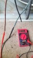
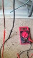
This is a condenser fan motor from a day and night ac unit it has 3 wires black brown and blue can anyone help me on how do I hook this up I'm using it as a fan for my shed so I do have 220volt plugs as well as 110volts
Attachments
-
 77 KB Views: 12
 -
 157.4 KB Views: 12