Trying to generate power from a coil and magnet

Thread Starter

Yawningtears

Joined Jul 16, 2020
42
The arrangements you show in post #50 are unlikely to generate more than a few microwatts of electrical power. They will all produce tiny AC voltages.
As for charging a car battery, let's do some sums:-
Assume a modest 12V 40Ah battery.
Storeable energy = 12V x 40Ah = 480Wh.
Let's be generous and assume you could generate 1milliwatt.
Time to charge battery = 480Wh / 1mW = 480,000 hours.
Now do you consider battery charging would be practical?
Can you do the math with what was demonstrated in the video, 277 milliamperes when he hit it, how bout let’s say 100 milliamps to be conservative?
correct me if I’m wrong here, my algebra could easily be

100 milliamps = 100 milliwatts/volt

120v x 100 milliamps = 12,000 milliwatts = 12 watts

if that translates, then wouldn’t it then only take 480Wh/12W = 40hours to charge?
I have a feeling my math is off some how
 

Thread Starter

Yawningtears

Joined Jul 16, 2020
42
I believe that with so many replies you got, the only real option is to stop opposing you arguments / reasons and doing a basic test with a coil of, say, 100 turns and a magnet going inside our repeatedly or just passing in front (of the coil) back and forth in regular fashion. With a multimeter at the coil's terminal try to visualize the changes in voltage you could see. Then, try to do the same with the DMM connected to measure current.
Add a resistor of 1K or even a LED, make notes and try to get some conclusions. Then come back with that.

If you keep talking, I could tell you nice fairy tales or provide links to those illuminatti posting pure crap in Youtube.

For your reference, the "discovery" of an incredible source of free energy by harvesting like the one created by people walking in the streets, stepping on piezoelectric devices, is recurrent. You see that in newspapers, TV and of course YT showing up from time to time. Be realistic.
I would love to test it and have been asking countless times now for a referral to a coil I can buy yet have still not been linked to one, if I knew what to get and experiment with, I wouldn’t have asked or started this thread in the first place.
 

hexreader

Joined Apr 16, 2011
619
Did you read the comments that went with the video?

The presenter admits that he was reading the ammeter incorrectly. The coil produced 277 microAmps, not 277 milliAmps.

If only the presenter had measured the milliVolts, as well as the microAmps, there might be some approximation of power produced, but he didn't. I will make a guess at 0.1 Volts across the coil, so 0.277mA x 0.1V = 27.7 microWatts by my estimation.

12 Watts is a completely bonkers estimation for that set-up. Dream on....

(all estimated values are AC RMS)
 
Last edited:

MrAl

Joined Jun 17, 2014
13,765
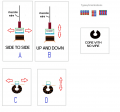
View attachment 212392
Ok, hopefully this will clear up some confusion and help me figure this out as I don’t really know this stuff.

Not sure which if any orientation and type would be the best combo or even work to generate electricity.

Please excuse my childish, amateur drawings, but I hope this helps make a lil more sense of what I’m trying to do.

*Note, the inductor would be mounted/fixed if that wasn’t clear.
Hello again,

That is a good diagram, however it is not yet entirely clear how the magnet is to move relative to the core and/or gap. This information is needed to determine what inductor and magnet would be best.

In this new diagram, is "A" correct or is "B" correct, and is "C" correct or is "D" correct? (Note A and B and C and D refer to the new drawings)

I am asking because usually muscle wire contracts and expands it does not wiggle side to side, but you might clarify which it is. This is in reference to the movement of the magnet not the wire itself.
MuscleWireGenerator-2.png
 
Last edited:

djsfantasi

Joined Apr 11, 2010
9,237
Hello again,

That is a good diagram, however it is not yet entirely clear how the magnet is to move relative to the core and/or gap. This information is needed to determine what inductor and magnet would be best.

In this new diagram, is "A" correct or is "B" correct, and is "C" correct or is "D" correct?

I am asking because usually muscle wire contracts and expands it does not wiggle side to side, but you might clarify which it is.
I have a question, to which I’ve previously assumed the answer to be no. When you write muscle wire, are you referring to nitinol? Because the Power necessary to move the muscle wire is 10 times, if not significantly more, than any power you can generate.
 

Thread Starter

Yawningtears

Joined Jul 16, 2020
42
Did you read the comments that went with the video?

The presenter admits that he was reading the ammeter incorrectly. The coil produced 277 microAmps, not 277 milliAmps.

If only the presenter had measured the milliVolts, as well as the microAmps, there might be some approximation of power produced, but he didn't. I will make a guess at 0.1 Volts across the coil, so 0.277mA x 0.1V = 27.7 microWatts by my estimation.

12 Watts is a completely bonkers estimation for that set-up. Dream on....

(all estimated values are AC RMS)
I have read through a ton of comments and could only find one that was wondering if it was micro or milliamps, it is hard to see exactly in the video, I can’t tell if there are multiple commas or if it’s one comma, and one decimal, so while it could be microamps, I couldn’t find anything definitive that it was.
 

hexreader

Joined Apr 16, 2011
619
You seem determined to believe what you want to believe. :(
Good luck with continuing to delude yourself. 12W is monster-raving-loony bonkers

Do what the presenter tells you to do and strip a turn-table motor out of a scrap microwave oven and learn for yourself.
 
Last edited:

MrAl

Joined Jun 17, 2014
13,765
I have a question, to which I’ve previously assumed the answer to be no. When you write muscle wire, are you referring to nitinol? Because the Power necessary to move the muscle wire is 10 times, if not significantly more, than any power you can generate.
The way i understood it is that the movement is occurring through some other already established process, and the idea is to extract some energy from that process.
However, extracting energy from a movement of some type will also have a viscous damper effect which will either start to limit the movement, slow it down, or require more applied force.

It could also be just part of an experiment where the muscle wire mimics some natural process and the idea is to see how hard it would be to extract power from that process without having to actually have that process present or be at the actual site of where the real process is taking place.
 

Thread Starter

Yawningtears

Joined Jul 16, 2020
42
Hello again,

That is a good diagram, however it is not yet entirely clear how the magnet is to move relative to the core and/or gap. This information is needed to determine what inductor and magnet would be best.

In this new diagram, is "A" correct or is "B" correct, and is "C" correct or is "D" correct? (Note A and B and C and D refer to the new drawings)

I am asking because usually muscle wire contracts and expands it does not wiggle side to side, but you might clarify which it is.View attachment 212430
I don’t know too much about artificial muscles, but in this setup, I did assume it would move side to side, not contract and expand. So in that case, I figured it would make the magnet “wiggle” with the flexibility of the rubber where the sides of the magnet move up and down, I tried to show that in my diagram but it was a lil tough.

So, not really A or B.

HOWEVER, I could be completely wrong with my assumption about how it is “working” in that video, maybe the “artificial muscle” is actually contracting/expanding and the magnet is moving like B. I thought it might be like a spring on its side that could flex/wobble.

As for C or D, that is my question I would be asking you, I don’t know which is the best way to orient that type of inductor.
 

Thread Starter

Yawningtears

Joined Jul 16, 2020
42
You seem determined to believe what you want to believe. :(
Good luck with continuing to delude yourself. 12W is monster-raving-loony bonkers
The ultimate point, from my first post, is to figure out an inductor and then I can test it and come back here and say you were right, care to help me find one?
 

Audioguru again

Joined Oct 21, 2019
6,826
The current shown on the multimeter in the video was 0.188mA for only a moment when it was hit fairly hard.
0.188mA is only 188uA which is very close to nothing. The voltage was also almost nothing.
 

Thread Starter

Yawningtears

Joined Jul 16, 2020
42
I have a question, to which I’ve previously assumed the answer to be no. When you write muscle wire, are you referring to nitinol? Because the Power necessary to move the muscle wire is 10 times, if not significantly more, than any power you can generate.
I was reading comments on the video and someone else mentioned nitinol, but honestly, I really don’t know much about them.
 

Thread Starter

Yawningtears

Joined Jul 16, 2020
42
The current shown on the multimeter in the video was 0.188mA for only a moment when it was hit fairly hard.
0.188mA is only 188uA which is very close to nothing. The voltage was also almost nothing.
You could very well be right, for me, it’s hard to see it, it looks like there are two decimals or commas... I don’t know that meter, but is it common to have two decimals?
 

Thread Starter

Yawningtears

Joined Jul 16, 2020
42
Presenter already explained that the coil comes from a scrap microwave oven - the turn-table motor.
Do you know where I can so easily buy that or what I would search for without having to buy a whole microwave?

update: I actually found some, they aren’t super cheap, let’s avg say $10 per... it would be nice to get a set of 10 inductors that are similar for maybe let’s say $15 or something like that.
 
Last edited:

hexreader

Joined Apr 16, 2011
619
I don’t know that meter, but is it common to have two decimals?
I own the same meter, it has one decimal and one comma. The current is definitely, 100%, without doubt, less than one milliAmp, exactly as the presenter admits to.

What is unknown is the voltage and duration, so average power cannot be determined from the information in that video, but trust the forum members here that the power is negligible, however well you build the device.

Let us know how the experimenting goes.....
 

Thread Starter

Yawningtears

Joined Jul 16, 2020
42
I own the same meter, it has one decimal and one comma. The current is definitely, 100%, without doubt, less than one milliAmp, exactly as the presenter admits to.

What is unknown is the voltage and duration, so average power cannot be determined from the information in that video, but trust the forum members here that the power is negligible, however well you build the device.

Let us know how the experimenting goes.....
Well ok but that is a lil confusing then, usually commas are left of decimals and the 200+/- on his meter was left of the right dot which I’m assuming is the decimal. Meaning it would be 200 mA, not .200 mA. But you have one and would obv know better but it doesnt make sense to me.

I could not find anywhere where the presenter admitted to it being .200

I would like to expiriment, you wouldn’t happen to know a cheaper option to that turn table motor for an inductor which might work the same would you?
 

hexreader

Joined Apr 16, 2011
619
dot on the left, comma on the right

No, I know of no source of suitable coil other than scrap. If you want to charge a car battery then you will need thousands of them.

Read the comments associated with the video for presenter's admission of micro/milli mistake - it really is there (more than once)
 

Thread Starter

Yawningtears

Joined Jul 16, 2020
42
dot on the left, comma on the right

No, I know of no source of suitable coil

Read the comments for presenter's admission of micro/milli mistake - it really is there (more than once)
I honestly looked thro so many comments, maybe cause I’m looking thro my phone’s app, but I couldn’t find it.
I guess I’ll take you’re word for it, Ive never seen where a comma is on the right side of the decimal but I can understand how that makes sense, I also would have figured he knew his own equipment
 

Alec_t

Joined Sep 17, 2013
15,149
Can you do the math with what was demonstrated in the video
No, because the video gives no indication of the generated voltage; it only gives an assumed peak current value. It's not known how the measuring instrument responds to a brief impulse, so that peak value is dubious. To calculate power you need to know Volts and Amps. Power = Volts x Amps.
 
Top