Trying to generate power from a coil and magnet

Thread Starter

Yawningtears

Joined Jul 16, 2020
42
No, because the video gives no indication of the generated voltage; it only gives an assumed peak current value. It's not known how the measuring instrument responds to a brief impulse, so that peak value is dubious. To calculate power you need to know Volts and Amps. Power = Volts x Amps.
Makes sense, don’t know why I didn’t even realize that, I do know voltsXamps...
 

hexreader

Joined Apr 16, 2011
619
Makes sense, don’t know why I didn’t even realize that, I do know voltsXamps...
Pity the presenter did not know "voltsXamps" (or in reality, millivoltsXmicroamps)
... might have made for a much more useful video.
;)
To be fair - the video provides thoughts and ideas, (but no useful substance).
Waffle is cheap - but if only he had connected a few thousand of those gadgets to a real bridge with moderate traffic in a moderate breeze to prove that the combined power could charge a mobile phone in under a day. :cool:
 

Thread Starter

Yawningtears

Joined Jul 16, 2020
42
The synchronous motors are anywhere from 2-4w approx from those microwaves, but I understand that’s power being fed to them and not what they would produce the other way around especially when modified...

But if somehow you could miraculously get two watts out of it, then 480wh battery would be charged in 280hrs?

or 28 of them in 10hrs?

I’m prob not realizing that those watts are from 120v, so it would take a lot in series to even get the bolts to get the 2 watts?
 

djsfantasi

Joined Apr 11, 2010
9,237
FYI, muscle wire, e.g. nitinol, expands when heated; contracts when cooled. So a piece of muscle wire inline with your magnets will push/pull, not ‘wiggle’, if mounted orthogonally, it could wiggle, but nitinol is a slow moving method of providing motion.

Nitinol has another property. It can be trained to make a shape. It can be stretched out and when heated, will return to the trained shape. Various spring shapes can be made.

In animation, heating is performed by running a current through the wire. But it takes a large current.
 

MrAl

Joined Jun 17, 2014
13,764
Pity the presenter did not know "voltsXamps" (or in reality, millivoltsXmicroamps)
... might have made for a much more useful video.
;)
To be fair - the video provides thoughts and ideas, (but no useful substance).
Waffle is cheap - but if only he had connected a few thousand of those gadgets to a real bridge with moderate traffic in a moderate breeze to prove that the combined power could charge a mobile phone in under a day. :cool:
You'd be surprised at how very poor many of the videos are on the web even made by supposedly very knowledgeable people in academia.
For example, videos that are supposed to show how the Lorentz force works with current and a magnetic field, yet they fail to show the polarity of the battery generating the current! So what they end up showing is, "Things move when you have a large magnet near a wire with a current in it" ha ha.
 

Thread Starter

Yawningtears

Joined Jul 16, 2020
42
FYI, muscle wire, e.g. nitinol, expands when heated; contracts when cooled. So a piece of muscle wire inline with your magnets will push/pull, not ‘wiggle’, if mounted orthogonally, it could wiggle, but nitinol is a slow moving method of providing motion.

Nitinol has another property. It can be trained to make a shape. It can be stretched out and when heated, will return to the trained shape. Various spring shapes can be made.

In animation, heating is performed by running a current through the wire. But it takes a large current.
Gotcha, I don’t think the guy used nitinol, I think he made his own using a nylon line, not sure about the the expansion or wiggles.
 

hexreader

Joined Apr 16, 2011
619
But if somehow you could miraculously get two watts out of it, then 480wh battery would be charged in 280hrs?
That assumes that you put significant power into driving the shaft, not a feeble breeze and a small amount of vibration. A feeble amount of power into any device will supply a feeble amount of power (less losses) out.

Maybe fit the microwave turn-table motor (attached in a clever way) under a bridge to catch significant power, but not the device shown in the video.

I suspect that reverse-feeding turn-table motor may be impractical or impossible due to high gearing ratio combined with friction.
 

AlbertHall

Joined Jun 4, 2014
12,640
Scrap microwave ovens seem to be widely available. They are used as source of transformers for modifying.
I got mine from freecycle.
 

MrAl

Joined Jun 17, 2014
13,764
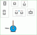
I don’t know too much about artificial muscles, but in this setup, I did assume it would move side to side, not contract and expand. So in that case, I figured it would make the magnet “wiggle” with the flexibility of the rubber where the sides of the magnet move up and down, I tried to show that in my diagram but it was a lil tough.

So, not really A or B.

HOWEVER, I could be completely wrong with my assumption about how it is “working” in that video, maybe the “artificial muscle” is actually contracting/expanding and the magnet is moving like B. I thought it might be like a spring on its side that could flex/wobble.

As for C or D, that is my question I would be asking you, I don’t know which is the best way to orient that type of inductor.
Ok then how do you intend to test this thing if you dont have the setup already set up?

It sounds like you are in exploration mode where you just have to try things and see if anything works at all. If you are not sure of the movement then it makes it impossible to recommend anything so you just have to go on your own and experiment.

My best advice at this point is to get a silicon steel core either a "C" core or just a straight core like you find with an EI core just using the I part, and layer some good tape (like mylar or similar) around the core and then wind as many turns as you can.
The magnet would be oriented at the top such that the N and S poles are side to side, so that when the magnet moves from side to side so when it moves left the N pole gets closer to the core end and then when it moves right the S pole gets closer to the end of the core piece. The idea is to orient the magnet so that first the N side is closer then when it moves the other way the S pole is closer. That varies the flux in both directions and will produce an AC current in the coil around the core.
Silicon steel is highly magnetically active so you might get some decent results although the amount of movement is going to determine just how well this works. Do a few measurements and see what you think. Keep in mind that the movement of the muscle wire may diminish once you try to draw some current from the wire to power something like an LED or resistor. The power draw feeds back to the mechanical movement and if the force is too low it may move very little even though with no current draw it moves freely. The magnet is going to be attracted to the core material too so that will cause a diminished movement unless the force from the wire is significant, but that attraction is necessary in order to get the flux to vary through the core and thus produce current.

You might try this for a core:
https://www.nicore.com.cn/Silicon-Steel-Cores-html

When i was working in the industry we used to buy cores from Magnetics Inc but they may only sell in large quantities unless you can still ask for samples. I was able to get a lot of free samples from them but that was some 20 years ago.

You can even use a soft steel nail like a 10 penny nail but the permeability is fairly low (like 100) compared to silicon steel (2000 or better). The higher permeability works much better.

This is a difficult setup dimensionally because usually we can get the magnet to change polarity by rotating it. This makes me think that maybe there would be a solution where the muscle wire movement is connected to the magnet with some mechanical linkage that makes it rotate clockwise and counter clockwise, although it would have to be low friction and low mass. Side to side movement is harder to capture because we have to continuously change the magnetic polarity in order to generate current in a wire.
 

Thread Starter

Yawningtears

Joined Jul 16, 2020
42
Ok then how do you intend to test this thing if you dont have the setup already set up?

It sounds like you are in exploration mode where you just have to try things and see if anything works at all. If you are not sure of the movement then it makes it impossible to recommend anything so you just have to go on your own and experiment.

My best advice at this point is to get a silicon steel core either a "C" core or just a straight core like you find with an EI core just using the I part, and layer some good tape (like mylar or similar) around the core and then wind as many turns as you can.
The magnet would be oriented at the top such that the N and S poles are side to side, so that when the magnet moves from side to side so when it moves left the N pole gets closer to the core end and then when it moves right the S pole gets closer to the end of the core piece. The idea is to orient the magnet so that first the N side is closer then when it moves the other way the S pole is closer. That varies the flux in both directions and will produce an AC current in the coil around the core.
Silicon steel is highly magnetically active so you might get some decent results although the amount of movement is going to determine just how well this works. Do a few measurements and see what you think. Keep in mind that the movement of the muscle wire may diminish once you try to draw some current from the wire to power something like an LED or resistor. The power draw feeds back to the mechanical movement and if the force is too low it may move very little even though with no current draw it moves freely. The magnet is going to be attracted to the core material too so that will cause a diminished movement unless the force from the wire is significant, but that attraction is necessary in order to get the flux to vary through the core and thus produce current.

You might try this for a core:
https://www.nicore.com.cn/Silicon-Steel-Cores-html

When i was working in the industry we used to buy cores from Magnetics Inc but they may only sell in large quantities unless you can still ask for samples. I was able to get a lot of free samples from them but that was some 20 years ago.

You can even use a soft steel nail like a 10 penny nail but the permeability is fairly low (like 100) compared to silicon steel (2000 or better). The higher permeability works much better.

This is a difficult setup dimensionally because usually we can get the magnet to change polarity by rotating it. This makes me think that maybe there would be a solution where the muscle wire movement is connected to the magnet with some mechanical linkage that makes it rotate clockwise and counter clockwise, although it would have to be low friction and low mass. Side to side movement is harder to capture because we have to continuously change the magnetic polarity in order to generate current in a wire.
Thanks man, really appreciate your help!

many thoughts on c type inductor orientation relative to the magnet?
 

MrAl

Joined Jun 17, 2014
13,764
Thanks man, really appreciate your help!

many thoughts on c type inductor orientation relative to the magnet?
Hi,

Well, with a straight vertical oriented core with two open ends, the best bet is to polarize the top N and the bottom S, then reverse with S on top and N on the bottom end, then repeat that constantly. You would try to get as close to that scenario as possible.
With a "C" core, it also has two open ends, so it is the same except the two ends happen to both be 'up' if the core is oriented as a "U". One end N and the other S, then reverse as with the straight core.

The ultimate with a C core would be to have the two halves (there are two halves to each core) joined together but with one end of one of the C halves ground down so that you get a 'gap'. The magnet is then oriented horizontally with say N on left and S on right, and moved back and forth over the gap. Since the movement is so small though it will not completely reverse the flux in the core it will just make it higher and lower which is not as good but hard to get around if you dont use a rotating mechanism. This is like the way a recording tape head works as the polarized particles move past the head. That only has to develop a small signal though.

So you see what we are up against. The limited movement is very hard to deal with using magnetic devices where you want to extract a significant amount of power because it is hard to get the flux to reverse (and that takes full advantage of the properties of the core material vs just unipolar increasing and decreasing the flux).
The advantage is that it will not slow down or impede the movement as much.

Using a piezo device small movements are very typical, but then larger forces are expected along with that.

Here is what might be an interesting idea, although i am not sure what you can modify in the original setup...
If you had one muscle fiber pulling the top N to the left until it was horizontal, then have another fiber pull the top to the right, and had the C core oriented as a U underneath, that would completely reverse the magnet polarity relative to the U core. The magnet would rotate 180 degrees, then back 180 degrees, then repeat, so it would be mounted on a short shaft that allows it to rotate at the center of the N and S poles. That could work fairly well.
 
Last edited:

Thread Starter

Yawningtears

Joined Jul 16, 2020
42
Hi,

Well, with a straight vertical oriented core with two open ends, the best bet is to polarize the top N and the bottom S, then reverse with S on top and N on the bottom end, then repeat that constantly. You would try to get as close to that scenario as possible.
With a "C" core, it also has two open ends, so it is the same except the two ends happen to both be 'up' if the core is oriented as a "U". One end N and the other S, then reverse as with the straight core.

The ultimate with a C core would be to have the two halves (there are two halves to each core) joined together but with one end of one of the C halves ground down so that you get a 'gap'. The magnet is then oriented horizontally with say N on left and S on right, and moved back and forth over the gap. Since the movement is so small though it will not completely reverse the flux in the core it will just make it higher and lower which is not as good but hard to get around if you dont use a rotating mechanism. This is like the way a recording tape head works as the polarized particles move past the head. That only has to develop a small signal though.

So you see what we are up against. The limited movement is very hard to deal with using magnetic devices where you want to extract a significant amount of power because it is hard to get the flux to reverse (and that takes full advantage of the properties of the core material vs just unipolar increasing and decreasing the flux).
The advantage is that it will not slow down or impede the movement as much.

Using a piezo device small movements are very typical, but then larger forces are expected along with that.

Here is what might be an interesting idea, although i am not sure what you can modify in the original setup...
If you had one muscle fiber pulling the top N to the left until it was horizontal, then have another fiber pull the top to the right, and had the C core oriented as a U underneath, that would completely reverse the magnet polarity relative to the U core. The magnet would rotate 180 degrees, then back 180 degrees, then repeat, so it would be mounted on a short shaft that allows it to rotate at the center of the N and S poles. That could work fairly well.
Hmm, I may or may not be understanding it, would my diagrams be ok for reference? I put the magnets and the C core in a few different orientations, were you suggesting a any of those? The A, B, and C also apply to the cores, and with B and C, if you notice I put the magnets in different relative positions to the core.
 

MrAl

Joined Jun 17, 2014
13,764
Hmm, I may or may not be understanding it, would my diagrams be ok for reference? I put the magnets and the C core in a few different orientations, were you suggesting a any of those? The A, B, and C also apply to the cores, and with B and C, if you notice I put the magnets in different relative positions to the core.
Yes the C core is oriented as a U that means open end up.
The magnet is suspended over the open end so that it can rotate where the N pole gets close to one end of the core while the S pole gets close to the other end. The direction of rotation is then reversed. I can draw a diagram if you cant picture this yet.

Also, with a small motor you can mount a lever on the shaft and rock that back and forth. That would probably be a good idea because the motor will already be designed with the right kind of core material and coils of wire and very little gap between the N and S poles and the core poles.

Also we have to keep in mind that the mechanical equivalent is 1 hp equals about 750 watts, so if you have 1/10 hp you can only get 75 watts, and with 1/100hp only 7.5 watts, and with 1/1000 hp only 0.75 watts, and with 1/10000hp only 0.075 watts, and with 1/100000hp only 0.0075 watts. There is absolutely no way around that.
(hp is horsepower)
 

Thread Starter

Yawningtears

Joined Jul 16, 2020
42
Yes the C core is oriented as a U that means open end up.
The magnet is suspended over the open end so that it can rotate where the N pole gets close to one end of the core while the S pole gets close to the other end. The direction of rotation is then reversed. I can draw a diagram if you cant picture this yet.

Also, with a small motor you can mount a lever on the shaft and rock that back and forth. That would probably be a good idea because the motor will already be designed with the right kind of core material and coils of wire and very little gap between the N and S poles and the core poles.

Also we have to keep in mind that the mechanical equivalent is 1 hp equals about 750 watts, so if you have 1/10 hp you can only get 75 watts, and with 1/100hp only 7.5 watts, and with 1/1000 hp only 0.75 watts, and with 1/10000hp only 0.075 watts, and with 1/100000hp only 0.0075 watts. There is absolutely no way around that.
(hp is horsepower)
Ok, thanks, I will see what I can put together.
 

shortbus

Joined Sep 30, 2009
10,049
If your wanting to make electricity with vibrations you might want to rethink how your doing it. Inmstead of moving the magnet near a coil, why not do it like they do with an electric guitar pickup? In them the coil is wound around the magnet and the wire vibrates over top of the magnet. Doing that only needs to vibrate the magnetic field, not the whole magnet.

Just one of the many many sites explaining the process of the pickup - https://www.guitarworld.com/gear/how-does-a-guitar-pickup-really-work
 

Thread Starter

Yawningtears

Joined Jul 16, 2020
42
If your wanting to make electricity with vibrations you might want to rethink how your doing it. Inmstead of moving the magnet near a coil, why not do it like they do with an electric guitar pickup? In them the coil is wound around the magnet and the wire vibrates over top of the magnet. Doing that only needs to vibrate the magnetic field, not the whole magnet.

Just one of the many many sites explaining the process of the pickup - https://www.guitarworld.com/gear/how-does-a-guitar-pickup-really-work
I will check it out, thx
 

MrAl

Joined Jun 17, 2014
13,764
Wow thanks, so any of those arrangements would work?

Some better than others I assume?
Hi,

Yes. And the one on the far left is just showing what the C core looked like when it is put together and when the two halves are separated.

On the right, the one with the gap on the far right probably works the best of that kind that does not rotate the magnet completely, but creating a gap may not be easy. Usually the gap is machined often by the company who makes the core.
The one in the center that rotates could work pretty well but it requires some mechanical linkage to get 180 degree back and forth rotation movement from a small side to side movement.

The "motor" could work good but it depends on the motor and how the shaft is oriented at mid travel.

All types would output an AC current. Could the motor type output DC? It might be able to if the travel distance is significant and the shaft is oriented just right at mid travel. With very small movements that may be hard to achieve though, depending on the motor size and commutator.
 

MrChips

Joined Oct 2, 2009
35,018
TS is missing some vital pieces of information which make this experiment futile.

1) Any generated voltage will be AC. TS does not fully understand how to convert from AC to DC. The standard way is to use diode rectifiers. 1N4001 type diodes have forward voltage of about 0.7V. Schottky diodes such as 1N4817 have a forward voltage of about 0.3V. In either case, the voltage from the coil has to exceed the diode forward voltage before rectification will occur.

2) The gentleman in the video connected an ammeter to the coil in order to measure current. He did not measure voltage.
An ideal ammeter is a short circuit. The voltage across the ammeter is practically zero. Power generated = μA x 0V = 0W,
The experimenter needs to connect a load to the coil and then measure current and voltage.

3) The induced voltage is directly proportional to the number of turns in the coil. In order to generate any appreciable voltage you need lots of turns, into the ten's of thousands. In order to maintain a reasonably physically small coil, you need magnet wire of very small diameter. When you do that the DC resistance of the coil increases. Power generated is wasted as heat in the resistance of the coil.

4) TS does not know how to arrange the poles of a magnet in order to optimize the changing magnetic flux in the coil. If you want to learn how to get the maximum induced voltage study how a loudspeaker is designed, They are designed for maximum efficiency and power transfer.

5) The magnet will oscillate freely when there is no load connected to the coil and no current is generated. As soon as you connect a load to the coil a back EMF is generated which opposes the motion of the magnet. This is basic physics and the law of conservation of energy. Apply a heavy load and the magnet will stop oscillating. Have you ever tried to pedal a bicycle when the dynamo is engaged and the headlight is on?

This is my last word on this.
 
Top