Truth table for flip flop inputs

Thread Starter

coderSam1088

Joined Apr 25, 2022
4
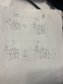
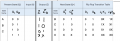
I am taking a logic design class, and the professor assigned a lab in the last week; since I am online I rely on videos and her video cut off before she went over this part, and I'm stuck. I need to create an algebraic expression for the attached table using JK flip flops. I was able to get J1K1 and J0K0, but not sure how this translates to a K-map. I looked at some things online and came up with a k-map (also attached), but I'm not sure if it's correct or how to put that in to an algebraic expression for J2K2 and J1K1 (those are not the inputs we used in the table, so not sure if there is a special reason why the numbering is different in the prompt) and I also don't know if I should be using one algebraic expression for both of them or putting them together. The instructions say "Using K-Maps, figure out the simplest Boolean Algebra Expression for JK Flip Flop Inputs J2K2 and J1K1". Any help would be appreciated. Thank you!
 

Attachments

dl324

Joined Mar 30, 2015
16,923
Welcome to AAC!
I looked at some things online and came up with a k-map (also attached), but I'm not sure if it's correct
Looks correct to me, but I ignored your output and transition information. I'm not sure why you're not being taught to use gray code for the truth table. Doing that makes it easier to transfer data from the table to kmaps.
I also don't know if I should be using one algebraic expression for both of them or putting them together.
They should be kept separate. If you label current and next state as Q1 and Q0, the inputs should be labeled J1/K1 and J0/K0, respectively, as you've done.
 

Thread Starter

coderSam1088

Joined Apr 25, 2022
4
Welcome to AAC!
Looks correct to me, but I ignored your output and transition information. I'm not sure why you're not being taught to use gray code for the truth table. Doing that makes it easier to transfer data from the table to kmaps.
They should be kept separate. If you label current and next state as Q1 and Q0, the inputs should be labeled J1/K1 and J0/K0, respectively, as you've done.
Thank you! I think I just need to transfer it to a diagram now. I am not sure if the lsb matters for the CD4027 chip, but I'm having trouble figuring out whether it's Q1 or Q2. It makes sense that it doesn't matter since they have their own clock, I think.
 

dl324

Joined Mar 30, 2015
16,923
I am not sure if the lsb matters for the CD4027 chip, but I'm having trouble figuring out whether it's Q1 or Q2.
The flip flops are independent and you can choose either one to be the LSB. The Motorola datasheet labels them A and B, but that has nothing to do with the way you connect them.
 

Thread Starter

coderSam1088

Joined Apr 25, 2022
4
I did a quartus simulation, and the results are wrong. I realized I was supposed to be making it have result output 1, 2, 3 (or 01, 10, 11), so the initial k-maps were wrong, but either way it's not giving me the right output. I am not sure what to set the "set" and "reset" to. Do I make it so the starting value is 01, and then the J and K values determine the next clock value? It is not changing after the first value, and I'm not sure what I'm doing wrong. I think I need to use different values for set and reset, but I have no idea what to set it to because she cut off the video before getting to that part.

Quartus simulation:1650917764070.png

VWF Output:
1650917818296.png

new Kmaps:
1650917905162.png
 

Attachments

dl324

Joined Mar 30, 2015
16,923
I think I need to use different values for set and reset, but I have no idea what to set it to because she cut off the video before getting to that part.
Set and reset on CD4027 are HIGH active, so you need them to be tied LOW.
1650923084352.png

Does the simulator you're using have a print to PDF option? If it does, you can get rid of the grid and multiple meaningless colors:
1650923392419.png
If you connect everything with wires, it makes for a more understandable schematic.
 
Top