Troubleshooting potentiometer problem

Thread Starter

garyh

Joined Dec 20, 2008
17
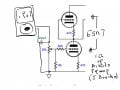
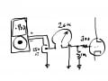
Hi, apologies if this is not the appropriate forum for this question...I am trying to troubleshoot an issue with a potentiometer between a tube preamp and source input. The issue is that the 20k Ohm pot measures correctly when not in circuit, and the wiper to ground/input measures correctly in its travel. When in circuit the resistance measured approaches just over 5k and then returns to 0 when turned clockwise, manifesting increasing volume to the halfway point, and then attenuation as the pot is turned from 12 o'clock to 5 o'clock. I am trying to resist the urge to just replace the pot until I understand the issue. The source (ipod dock) has a dc resistance of 250 Ohms and the input tube has a grid resistor of 300 Ohms, both seem pretty standard to me. The pot is isolated from chassis and signal ground connects to the preamp at one point only on the pcb. My guess is that this is a bad pot that misbehaves once there is current running through it. But most of my guesses in electronics are wrong. Any help is much appreciated.
 

MrChips

Joined Oct 2, 2009
30,708
No, the pot is not bad. What you have is a mismatch of resistances.
Ideally, you want the load resistance to be about 10 times larger than the source.

In your situation you do not have any room to maneuver.
Try a 1kΩ pot instead.
Is the 300Ω grid resistor between the grid and GND?
Can you remove the grid resistor?
 

Thread Starter

garyh

Joined Dec 20, 2008
17
No, the pot is not bad. What you have is a mismatch of resistances.
Ideally, you want the load resistance to be about 10 times larger than the source.

In your situation you do not have any room to maneuver.
Try a 1kΩ pot instead.
Is the 300Ω grid resistor between the grid and GND?
Can you remove the grid resistor?
thanks for the reply; there is a 1M resistor between pot/300R and ground. Can you explain a bit more about room to maneuver? In my reading on this, I gathered that I would need to go up in pot value to 100k, rather than down...which is due to impedance/low frequency loss issues. I'm guessing your hypothesis has nothing to do with this. Can you explain to me how the pot getting louder and then softer works? And why at full off I still hear some signal?
 

MrChips

Joined Oct 2, 2009
30,708
Do you have any info on the tube preamp, make, model number, circuit diagrams?
Do you have a diagram of how you wired the pot?

Tube circuits usually have high input impedance, greater than 100kΩ.
This should work well with 250Ω source. Hence you need a pot with resistance greater than 2500Ω and your preamp has to be about 25000Ω which you do not have, as yet.
 

KeithWalker

Joined Jul 10, 2017
3,063
The pot is isolated from chassis and signal ground connects to the preamp at one point only on the pcb. My guess is that this is a bad pot that misbehaves once there is current running through it. But most of my guesses in electronics are wrong. Any help is much appreciated.
That sounds a little odd! How exactly do you have it connected?
The signal common of the i-pod should be connected to circuit common on the pre-amp and the bottom end of the pot. The signal from the i-pod should be connected to the top of the pot. The slider of the pot should be connected to the signal input of the pre-amp. That is not what you describe above!
 

Thread Starter

garyh

Joined Dec 20, 2008
17
thank you both for your help, and please forgive my confusing description. Here is a schematic of the part of the circuit. It is one version of the John Broskie Aikido preamp. I hope this clears things up
 

Attachments

MrChips

Joined Oct 2, 2009
30,708
Now that we have a circuit diagram, the 300Ω is in series with the grid input and has little effect.
The input impedance of the tube preamp is 1MΩ not 300Ω.

According to your drawing you have the pot wired correctly (except for the CCW rotation which could be your error in the drawing).

I would guess that the iPod jack is intended to drive earphones or ear buds.
Try putting about 33-100Ω across the output of the iPod.

You might want to try AC coupling the signal into the preamp.
Try a capacitor, about 1-10μF, in series with the input.
 

Thread Starter

garyh

Joined Dec 20, 2008
17
Thanks for the suggestions. The headphone connection is around 50 Ohms, but actually I am using the cradle, which bipasses the ipod headphone output and volume control. I measured the dc resistance at 258 Ohms. (Not sure how to calculate or measure impedance). I will try the cap on the input. I assume this is to block dc? How does this address the pot issue?
 

Dave Lowther

Joined Sep 8, 2016
224
The headphone connection is around 50 Ohms, but actually I am using the cradle, which bipasses the ipod headphone output and volume control. I measured the dc resistance at 258 Ohms. (Not sure how to calculate or measure impedance).
I don't think you have said what type of iPod you are using. I measured the audio output impedance on a iPod touch 3 30 pin connector and it was around 50 ohms. If you can measure the audio voltage output you can roughly measure the output impedance by putting a resistor across the output and seeing how much the voltage drops. If you use a variable resistor and adjust it so you get 1/2 the no load voltage then the output impedance will be roughly the same as the resistance of the variable resistor. It's not a good idea to try and measure the iPod output with the ohm setting on a multimeter.
 

MrChips

Joined Oct 2, 2009
30,708
You cannot measure output impedance with an ohmmeter.

As Dave said, measure the voltage output (while producing an output signal). Apply a resistor as load and adjust the resistance until the output voltage is half that of the unloaded signal.

Without knowing the output impedance, try a 100Ω resistor as a load.
 

Thread Starter

garyh

Joined Dec 20, 2008
17
The 100 Ohm resistor was a very close guess...I used a 196 and the Vrms went from 580mV unloaded to 280mV. Using Dave's plan, as this is nearly half, would that mean the iPod impedance is around 100 Ohms? Btw, I was using a 1k sine wave test tone as audio signal. And the iPod is an iPod Classic 160GB from 2009 (A1238)
 
Last edited:

Dave Lowther

Joined Sep 8, 2016
224
I used a 196 and the Vrms went from 580mV unloaded to 280mV. Using Dave's plan, as this is nearly half, would that mean the iPod impedance is around 100 Ohms?
As the voltage approximately halved, the output impedance is approximately the same as the value of the resistor you used.
 

MisterBill2

Joined Jan 23, 2018
18,167
Why are you going into an amplifier with a 6SN7 dual triode from the low impedance output of an Ipod?? That tube is a left over from WW2. Is it part of the amplifier that uses a 6SN7 driving a 6V6 tube? THat was a very old circuit back in 1960. So it seems a bit strange to me. The potentiometer is OK and so is the circuit but the rest of it seems sort of out of date. And the 300 ohm resistor in series with the grid isthereto keep the stage from oscillating.
 

Thread Starter

garyh

Joined Dec 20, 2008
17
Hi, out of date is my middle name. The Aikido circuit is a bit more modern than the 6sn7 tubes, and attempts to cancel out power supply noise as a design feature using 2 tubes per channel, (4 triodes). Check out the Tube CAD Journal for more info. As far as there being more contemporary solutions to preamplification I'm sure there are plenty. I can run the ipod straight into my lm3886 chip amp and it sounds great. I'm trying to explore the sonic qualities of tube technology and develop a subjective awareness of the benefits and downsides. To this end I am looking to better understand how circuits work rather than find the simplest or most recent technology. So, I have an iPod with music on it, a tube preamp I am trying to preamplify the music with mixed success, and a low watt transistor power amp to drive the music through my speakers. Which also sound great. I am open to suggestions.
 

MisterBill2

Joined Jan 23, 2018
18,167
OK, and thanks for the explanation. Evidently I misread the circuit. a bit. Going into a triode grid with a 1 meg resistor I suggest a capacitor, probably 0.047 mfd, as a standard value, other wise 0.050 mfd.
Cancelling power supply noise did become a problem with the silicon diode rectifiers, they switched off so abruptly. I think that I put a 110 ohm resistor in series to reduce the buzz. today I would use an RF choke if it was a problem.
 

Thread Starter

garyh

Joined Dec 20, 2008
17
Thanks. I have ordered some caps to try this. How does this explain/solve my issue with the 20k pot allowing signal to increase until halfway, then attenuating it the rest of the way? Btw, this was not frequency dependent, as it occurs with a 1k input signal as well as pink noise. I guess I dont yet understand the difference between resistance (local/pot voltage) and impedance (global/input frequency band)
 

MrChips

Joined Oct 2, 2009
30,708
What you have experienced cannot be explained with the information we have at this point.
Hold tight for now and let's see what develops further.

So far what we know is the iPod's output impedance is 200Ω while the tube preamp input impedance is 1MΩ. There is nothing unusual about this so far.

Sometimes we tend to use resistance and impedance interchangeably. Both have unit of ohm.
Impedance is the resistance to AC. A 100Ω resistor has resistance of 100Ω and impedance of 100Ω.
When you add an inductor or capacitor to a circuit you are introducing reactance. Reactance and resistance combined is impedance. Reactance is frequency dependent and can cause phase shifts in the signal. Hence reactance introduces a different kind of resistance that mathematically becomes very complex. Hence we need to use complex arithmetic to solve problems with impedance.

You cannot measure input and output resistance/impedance with an ohmmeter.
You can measure resistance of a component accurately only when it is disconnected from the rest of the circuit.

Have you tried putting a resistive load of 100-200Ω on the signal output of the cradle?
 

MisterBill2

Joined Jan 23, 2018
18,167
It may be that as the control is advanced farther the low resistance of the Ipod output is disturbing the grid bias, and that in turn is reducing the gain. There may even be a DC component along with the audio signal. So certainly adding a series capacitor so that it is AC coupled should change things.
 

Thread Starter

garyh

Joined Dec 20, 2008
17
Again, thank you all for your help and the generous explanation. Regarding the resistor and cradle, that is how I found the impedance above. I do not plan on using the headphone out for a variety of reasons. (If my math is correct, it is closer to 189 Ohms input impedance). And regarding the dc offset, I recently acquired an oscilloscope that registers dc coupling and there seems to be none showing up as the center of the 1 k signal sits at 0. I did find a 10 uf electrolytic cap in my tiny spare parts box. I read that one should use only polypropylene or metalized poly caps for input coupling…will the polarized cap be ok for test purposes?
 
Top