Troubleshooting homemade DC power supply

Thread Starter

alphorn_subw00f

Joined Sep 10, 2012
12
I've built a linear DC power supply to provide adjustable zero to +25 V DC and 0 to -25 V DC outputs using a LM317 regulator for the +ve side and a LM337 for the -ve side.

The problem I have at the moment is that when the -ve side is tested with a 470Ω external load resistor to simulate the external load I will be mainly using the power supply with, I can only get about -12 V across the resistor.

When I only have a multimeter across the -ve side I can get around -25 V no problem. Also the +ve side of my supply does not suffer from the same problem when tested with 470Ω external load resistor.

I would be very grateful for any troubleshooting tips, the only things that sprang to my mind so far are 1) bad solder joints causing high resistance somewhere in the LM337 external adjust loop or 2) bad LM337 regulator.
 

Thread Starter

alphorn_subw00f

Joined Sep 10, 2012
12
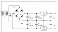
I don't have a proper full schematic for which I apologise, however my basic circuit design is as shown in 'Basic dc psu schematic.jpg' attached.

In my circuit IC1 is the LM317 and IC2 is the LM337, also my C1 and C2 are 2200 μF caps rather than 100 μF and my other caps are all 1 μF.

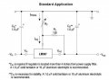
I've used the LM337 as shown in the attachment "lm337 standard application.jpg" except now I re-read the spec here I realise I have used only 1 μF caps (as these were to hand) instead of the recommended 10 μF - could that be part of the problem?

Many thanks!
 

Attachments

Papabravo

Joined Feb 24, 2006
22,111
12V and 470Ω is like 25 mA and the TO-220 package should handle a bit more. The regulators are adjustable but it won't take much current to make the very HOT with an input of say 28 Volts. Think about the power dissipated in the regulator.

Pd = (28V - 12V)*(.025 A) = 400 mW

That not an eye popping number but it is a significant fraction of what a TO-220 can handle without a heatsink. Increase the current demand to say 90 mA and you now have 1.44 Watts which WILL make the regulator finger-burny HOT

From the wikipedia article:

A TO-220 package that is not heatsinked typically dissipates around 1W of heat, at a temperature 62.5°C higher than the ambient temperature.
 

Thread Starter

alphorn_subw00f

Joined Sep 10, 2012
12
Thank you to all for the additional information and advice posted, much appreciated.

I have tested the voltages on the regulator input pins with and without the 470Ω external load resistor connected, as suggested, and results are as follows, where I attempted to set the output voltages of the +ve reg and the -ve reg to +25 V DC and -25 V DC respectively. (NB I found I could only get - 21.5 V DC from the -ve reg even with no external load).

No external load

+ve reg output pin = + 25.0 V DC
+ve reg input pin = + 47.5 V DC

-ve reg output pin = - 21.5 V DC (max neg voltage obtainable)
-ve reg input pin = -47.7 V DC

470Ω external load resistor connected

+ve reg output pin = + 25.1 V DC
+ve reg input pin = + 46.6 V DC

-ve reg output pin = -10.2 V DC
-ve reg input pin = -47.4 V DC

I've rechecked the LM337T pinouts against the data sheet and my circuit connections and it all seems to be correct as far as I can understand it.

I have got the regs mounted on heatsinks and I did briefly try the +ve reg at an output of around +35 V through the 470Ω resistor and both reg and resistor were getting pretty warm so I turned everthing down again! I ran the +ve reg at constant 15 V DC through the 470Ω load for an hour or so and there was no overheating problem, the reg was just about faintly warm to the touch.

Thanks in advance for any further troubleshooting help, I will try to post a photo of the built circuit.
 

Thread Starter

alphorn_subw00f

Joined Sep 10, 2012
12
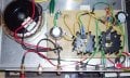
Here is a photo of the psu - I'm a complete novice so as you will see, my constructional skills are limited to say the least!

The LM337T is to the right of the LM317 (if you are looking at the photo with the front panel of the psu at the bottom).

There is a 1 μF cap which is not visible in this shot which is in parallel with the 2200 μF cap on the right hand side of the board for the LM337T input.

There are trimmer pots on the board which are connected in series with the rotary pots on the front panel.
 

Attachments

bertus

Joined Apr 5, 2008
23,000
Hello,

You are using the standard LM317 and LM337.
Those will go defective in case of a short, as the absolute maximum Vi-Vo voltage is 40 Volts.
Better use the LM317HV and LM337HV, the high voltage versions.
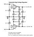
You can use this schematic to build the regulator:


Bertus
 

Attachments

Thread Starter

alphorn_subw00f

Joined Sep 10, 2012
12
Many thanks Bertus for your advice re the high voltage LM317/337 regulator versions, being naive to the subject I did not know about these and it sounds like they will be more robust for my application - and more immune to me creating inadvertent short-outs!

It sounds like I might have fried the LM337T which I was beginning to suspect, so I will try to get hold of the HV version and see how I go with that.
 

Thread Starter

alphorn_subw00f

Joined Sep 10, 2012
12
Yes I think I've probably had over 40 V between the reg input and output pins and damaged them - you live and learn!

I think I can set the trimmer pots in my circuit so that Vin - Vout shouldn't exceed 40 V, or alternatively invest in the 50 Volt-tolerant versions of the regs if I really want to get a 0 - 25 V output range.
 

Thread Starter

alphorn_subw00f

Joined Sep 10, 2012
12
Thank you for those datasheets bertus, much appreciated.

As I have one spare good LM337T left, I thought of one more thing to try before going to the HV regs, but any advice on whether this is sensible is welcome.

If I take the negative side rectifier output of approx -47 V DC and put a high resistance trimmer pot (5 MΩ?) across it as a potential divider, then tap off about -35V of that to be input into the LM337, will that still give me upto -25 V output from the regulator at a decent current while also providing a safety margin so that the reg can never get more than 35 V across it?
 

bertus

Joined Apr 5, 2008
23,000
Hello,

A resistor divider at the input will not work.
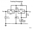
Perhaps a tracking preregulator might be a better idea:


If you make R2 about 2K2, the voltage on the second regulator will be about 12 Volts and the remaining voltage will go across the first regulator (as if it where a dynamic resistor).

Bertus
 

Attachments

Top