Facebook
 Google
 GitHub
 Linkedin
My check engine light came on a few months ago and I had the codes read at Autozone. I had a "knock sensor low voltage" code P0327. My truck ('05 GMC, 5.3L) has two knock sensors but only one of them was throwing a code. I went ahead and replaced both of them, plus the harness/pigtail that goes under the intake manifold. Disconnected the battery to reset the ECU, check engine light went away, but came back within 50 miles of driving. Had the codes read again, and now I'm getting the same low voltage code BOTH knock sensors.
Removing and reinstalling the intake manifold (actually all the crap on top of it) was quite a job, took several hours. I'd like to avoid doing that again if at all possible. I've been trying to figure out how these things work to know how to effectively troubleshoot them. Most of what I've read on car forums and seen on YouTube is coming from gearheads who have a basic understanding of what's going on, but still seem to be stabbing around in the dark because they don't have the proper tools. Most of them are using the $5 (or free) Harbor Freight DMM set to "AC Volts" to measure the output of the Piezo sensor which is in the kHz range. Some have said they replaced the sensor several times despite having "good" readings on the meter, and still can't get the codes to go away. I have read several times that only the factory knock sensors from the dealership should be used because the generic ones at autozone are manufactured to looser electrical tolerances which are appropriate for a wider range of vehicles. I used the ones from AutoZone; didn't know any better at the time.
The sensors have a 100kΩ resistor between the sensor wire and ground. Some gearheads say the ECU sends 5V to it, some say it sends 2.5V to it, some say the ECU doesn't send any voltage to it. My theory is that the resistor is part of a voltage divider with another 100kΩ resistor in the ECU; the ECU applies 5V and if the sensor is present, it should have 2.5V bias voltage on the input. Then the AC waveform from the piezo crystal in the sensor will be riding on top of this DC voltage. Is that correct?
If that's correct then maybe the bias voltage is just off a little bit. Maybe an external resistor either in series or parallel with the sensor could bring it back into spec and make the light go away. To be clear, I'm not proposing to "fake" the signal or bypass the sensor, as some have done by replacing the sensor with a resistor. I propose to correct the bias voltage with the sensor still in the circuit so that the ECU will see the proper AC waveform and won't get hung up on bias voltage.
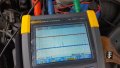
I haven't even put a DMM on the truck yet; maybe I'm getting ahead of myself. Just looking for some confirmation/correction of my theory and some pointers for this weekend when I break out the o-scope and start fiddling with it.
Removing and reinstalling the intake manifold (actually all the crap on top of it) was quite a job, took several hours. I'd like to avoid doing that again if at all possible. I've been trying to figure out how these things work to know how to effectively troubleshoot them. Most of what I've read on car forums and seen on YouTube is coming from gearheads who have a basic understanding of what's going on, but still seem to be stabbing around in the dark because they don't have the proper tools. Most of them are using the $5 (or free) Harbor Freight DMM set to "AC Volts" to measure the output of the Piezo sensor which is in the kHz range. Some have said they replaced the sensor several times despite having "good" readings on the meter, and still can't get the codes to go away. I have read several times that only the factory knock sensors from the dealership should be used because the generic ones at autozone are manufactured to looser electrical tolerances which are appropriate for a wider range of vehicles. I used the ones from AutoZone; didn't know any better at the time.
The sensors have a 100kΩ resistor between the sensor wire and ground. Some gearheads say the ECU sends 5V to it, some say it sends 2.5V to it, some say the ECU doesn't send any voltage to it. My theory is that the resistor is part of a voltage divider with another 100kΩ resistor in the ECU; the ECU applies 5V and if the sensor is present, it should have 2.5V bias voltage on the input. Then the AC waveform from the piezo crystal in the sensor will be riding on top of this DC voltage. Is that correct?
If that's correct then maybe the bias voltage is just off a little bit. Maybe an external resistor either in series or parallel with the sensor could bring it back into spec and make the light go away. To be clear, I'm not proposing to "fake" the signal or bypass the sensor, as some have done by replacing the sensor with a resistor. I propose to correct the bias voltage with the sensor still in the circuit so that the ECU will see the proper AC waveform and won't get hung up on bias voltage.
I haven't even put a DMM on the truck yet; maybe I'm getting ahead of myself. Just looking for some confirmation/correction of my theory and some pointers for this weekend when I break out the o-scope and start fiddling with it.