Troubleshoot Hisense fridge control board

Status
Not open for further replies.

Thread Starter

Teslacoil2000

Joined Sep 18, 2020
10
Hi all

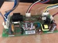
I have a Hi-Sense fridge with control board BCD-321WY/HC2 (EXH) for the past 18 months. Suddenly the fridge went completely dead, no signs of compressor running, no fan, no internal lights. I confirmed no problems with power and checked the fuse on the board, all ok.
I disconnecting the board and keeping it out of use for a 2-3 days, on re-connecting it works occasionally but stops after some time. Lights work, fan works and compressor cuts in for some time and stops in a few minutes. After some time no signs of life, everything including light is off.

I have checked the following
Functioning of compressor is OK. Cools down the fridge when run directly on mains supply (240V)
Fan in the freezer works well when run on a 12V DC supply from external power supply
Door switches for freezer and main compartment work well - tested by checking if fan stops when running on the board (not on external 12V supply)
Light works whenever the control board works
No components look burnt on the control board

I found some documentation for the board but it is in Chinese. Tried making sense of it using google translate but not very helpful.
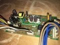
I have attached photos of the board (front and back) along with the documentation in Chinese.

Questions:
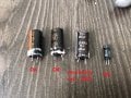
I checked the voltage on the primary side of the transformer. It is around 24V. Secondary side only shows about 2V.
Can someone let me know if the high voltage section of the transformer is a SMPS and functions to supply a lower (say 12v or 24v) to the low voltage section of the board.
Can i disconnect the transformer and try supplying a 12V DC supply directly at the transformer secondary contacts (transformer will be removed completely) to check if the low voltage sections control systems work. Can it cause any damage?
It will be very helpful if someone can explain the working of the primary side and any tips on what to check.

Thank you
 

Attachments

Tonyr1084

Joined Sep 24, 2015
7,853
While I probably can't help you fix the board (if that's the problem) - I can say this: When troubleshooting a board that is intermittent in failure it will be very hard to discern which component or section is failing. It sounds like a heat issue inside one of your components. One way we used to check for thermal failure of an intermittent component was to run the unit until it quit. Then using freeze spray, spray a single component one at a time to see if the unit begins working again. If you find a fault that way then you have a good idea what needs to be replaced. However, this must come with a warning - messing with a live board (240VAC Live Mains) is extremely dangerous. Likely no components on the board will operate at mains voltage except for the power supply. And if the entire unit quits at the same time then I'd be thinking the power supply may have issues. And sometimes the issue can be as simple as a cold or fractured solder joint. Very hard to find.

Got a TV (was "haunted") from a neighbor. The TV worked sometimes and sometimes it just had a horizontal line across the middle of the screen. I knew immediately it was probably a bad solder joint. Mostly because he'd whack it on the side and the TV would work again. The "Haunting" came in the fact that after 15 minutes of operation it would shut itself off. So I got to work. Reflowed every solder joint on the horizontal circuit. That solved the line problem. However, the 15 minute thing ? ? ? That was the sleep timer. Nothing haunting about that. So if you have a reoccurring failure after a short period of time it could be a failing component or a bad solder joint(s).

Fully diagnose the problem before you begin ordering parts.
 

Thread Starter

Teslacoil2000

Joined Sep 18, 2020
10
While I probably can't help you fix the board (if that's the problem) - I can say this: When troubleshooting a board that is intermittent in failure it will be very hard to discern which component or section is failing. It sounds like a heat issue inside one of your components. One way we used to check for thermal failure of an intermittent component was to run the unit until it quit. Then using freeze spray, spray a single component one at a time to see if the unit begins working again. If you find a fault that way then you have a good idea what needs to be replaced. However, this must come with a warning - messing with a live board (240VAC Live Mains) is extremely dangerous. Likely no components on the board will operate at mains voltage except for the power supply. And if the entire unit quits at the same time then I'd be thinking the power supply may have issues. And sometimes the issue can be as simple as a cold or fractured solder joint. Very hard to find.

Got a TV (was "haunted") from a neighbor. The TV worked sometimes and sometimes it just had a horizontal line across the middle of the screen. I knew immediately it was probably a bad solder joint. Mostly because he'd whack it on the side and the TV would work again. The "Haunting" came in the fact that after 15 minutes of operation it would shut itself off. So I got to work. Reflowed every solder joint on the horizontal circuit. That solved the line problem. However, the 15 minute thing ? ? ? That was the sleep timer. Nothing haunting about that. So if you have a reoccurring failure after a short period of time it could be a failing component or a bad solder joint(s).

Fully diagnose the problem before you begin ordering parts.
Thank you Tonyr1084.

I will check for bad solder and for heat issue. There are no external signs of heat related failure but i cannot be very sure.
 

Dodgydave

Joined Jun 22, 2012
11,285
Yes it's a Switchmode PSU, IC2 is the control chip with one output , when it is faulty is the 12V still there ?

What is the 30 pin chip for on the track side, any digital display or temperature control?
 

debe

Joined Sep 21, 2010
1,389
Check or just replace the marked condencers in the SMPS. If you want to bypass the SMPS, just lift the marked end of the diode just to the right of the transformer. Then feed 12V dc to the capacitor alongside.Whirlpool Hisense Fridge Control Board.jpg
 

Thread Starter

Teslacoil2000

Joined Sep 18, 2020
10
Yes it's a Switchmode PSU, IC2 is the control chip with one output , when it is faulty is the 12V still there ?

What is the 30 pin chip for on the track side, any digital display or temperature control?
Sorry for my late reply. The 30Pin chip is marked R5F102AAA. There are no digital display but there is a control for increasing or decreasing cooling. Not marked in C or F.

IC2 is the control chip with one output , when it is faulty is the 12V still there ? - I dont understand this. What and where do i check?
 

Thread Starter

Teslacoil2000

Joined Sep 18, 2020
10
Check or just replace the marked condencers in the SMPS. If you want to bypass the SMPS, just lift the marked end of the diode just to the right of the transformer. Then feed 12V dc to the capacitor alongside.View attachment 217595
Sorry for the late reply. I de-soldered the secondary section of transformer before reading your reply, your suggestion is far easier.

Had difficulty removing the secondary part and broke one pin (oops). Connected a 12V DC supply and it seems to be working on initial testing without any 220V supply on the HV side for compressor. I will test it further
 

debe

Joined Sep 21, 2010
1,389
If you have wrecked the transformer, & feeding 12V dc to the board makes it work. Then the easiest set up is use a 12V 1A DC plug pack to power it. Thats what i did to a similar problem to a fridge to get it working again.
 

Thread Starter

Teslacoil2000

Joined Sep 18, 2020
10
If you have wrecked the transformer, & feeding 12V dc to the board makes it work. Then the easiest set up is use a 12V 1A DC plug pack to power it. Thats what i did to a similar problem to a fridge to get it working again.
I managed to put the pin back in and have resoldered the wire from transformer coil to the pin. Checked with multimeter and it seems ok.
I have ordered some capacitors to replace the ones you suggested I change. Will get those by end of this week. I will then put the capacitors and transformer back to test. Will update again next weekend after I get the parts.
If that does not work, I will buy a small 12v 1A power supply and install it permanently connected to the control board.

Meanwhile I am running the fridge with a spare 12v 5A external supply connected to the secondary contacts of transformer and it seems to be working well. Running for more than 12 hours, maintains temperature and compressor cuts in and off as necessary. All other controls, lights, fan works as designed.
 

Thread Starter

Teslacoil2000

Joined Sep 18, 2020
10
If you have wrecked the transformer, & feeding 12V dc to the board makes it work. Then the easiest set up is use a 12V 1A DC plug pack to power it. Thats what i did to a similar problem to a fridge to get it working again.
Wrote my long reply previously but forgot to thank you. Thanks a lot for your suggestions and for the help
 

MisterBill2

Joined Jan 23, 2018
18,176
You may have an intermittent connection of the wire in one of the multi-pin connectors. That may be hard to find. It might be a bad solder connection on the bottom of the circuit board, THAT is simple and easy to fix, just a very few minutes to resolder them all.
 

Thread Starter

Teslacoil2000

Joined Sep 18, 2020
10
If you have wrecked the transformer, & feeding 12V dc to the board makes it work. Then the easiest set up is use a 12V 1A DC plug pack to power it. Thats what i did to a similar problem to a fridge to get it working again.
UPDATE:

I changed the capacitors you mentioned and also changed one additional on the 12v side immediately after the transformer on secondary side. Fridge is under test and seems to be working well for the past 3 hours.

The 3 capacitors on the primary side tested within limits after removal however the one on secondary was way off.

6.8MicroF 450V - Tested cap 1 as 6.89 MicroF & cap 2 as 6.90 MicroF
10 MicroF 50V - Tested as 9.51 MicroF
Secondary side cap 680 MicroF 25V tested as 764 mF (milli Farad not micro)

Question:
1. If the secondary cap was so off, can anyone help me understand how the board work well with my spare 12V power supply when this bad secondary capacitor was in use.
2. Can this bad capacitor be the source of problems for me? I hope it is not just working intermittently and may end up giving me problems later

Again, thanks a lot to everyone for your help. I would have had to replace the fridge because of this as the service center did not have a spare board and they quoted $250+tax to source it with 3 weeks delivery time.
 

Attachments

MisterBill2

Joined Jan 23, 2018
18,176
A filter capacitor is not a closely calibrated application. At one point I have seen them listed with a tolerance specification of +80%/-20%, which is quite usable. How are you checking the capacitor values? With some testers leakage current will alter the reading, also internal series resistance.
So please let us know how you checked the capacitors.
 

Thread Starter

Teslacoil2000

Joined Sep 18, 2020
10
A filter capacitor is not a closely calibrated application. At one point I have seen them listed with a tolerance specification of +80%/-20%, which is quite usable. How are you checking the capacitor values? With some testers leakage current will alter the reading, also internal series resistance.
So please let us know how you checked the capacitors.
I just used a multimeter to check across the capacitor terminals after they were removed from the board.

I checked the new ones as well before soldering them on the board, all were within close range of the number printed on the capacitor.
 

Thread Starter

Teslacoil2000

Joined Sep 18, 2020
10
UPDATE:

I changed the capacitors you mentioned and also changed one additional on the 12v side immediately after the transformer on secondary side. Fridge is under test and seems to be working well for the past 3 hours.

The 3 capacitors on the primary side tested within limits after removal however the one on secondary was way off.

6.8MicroF 450V - Tested cap 1 as 6.89 MicroF & cap 2 as 6.90 MicroF
10 MicroF 50V - Tested as 9.51 MicroF
Secondary side cap 680 MicroF 25V tested as 764 mF (milli Farad not micro)

Question:
1. If the secondary cap was so off, can anyone help me understand how the board work well with my spare 12V power supply when this bad secondary capacitor was in use.
2. Can this bad capacitor be the source of problems for me? I hope it is not just working intermittently and may end up giving me problems later

Again, thanks a lot to everyone for your help. I would have had to replace the fridge because of this as the service center did not have a spare board and they quoted $250+tax to source it with 3 weeks delivery time.
Hello all.

Any suggestions or answers to the above?
Thank you
 

debe

Joined Sep 21, 2010
1,389
The way you have tested the capacitors realy tells us nothing. In SMPS the ESR reading of the capacitor is more important than the actual capacity. The power supply you used would have had a decent size capacitor on the out put. Also the power supply you used has a lot more grunt than the one in the fridge circuit.
 

MisterBill2

Joined Jan 23, 2018
18,176
If the system continues to perform satisfactorily then probably it is fixed. It is always strange to have fixed a problem without knowing just what part was failed, but certainly not the first time that it has happened.
 

Thread Starter

Teslacoil2000

Joined Sep 18, 2020
10
Thank you @debe and @MisterBill2

The fridge continues to work well till now. I think I will leave it at that. Hopefully it works well long term and not have intermittent issues every few months.

Thanks again for all your support.
 

Tonyr1084

Joined Sep 24, 2015
7,853
@jibs The thread starter hasn't visited since October 9, 2020. I doubt you're going to get an answer.

BTW: Welcome to AAC.

If you need help with anything feel free to create your own thread.
 
Status
Not open for further replies.
Top