 Facebook
 Google
 GitHub
 Linkedin
Hi folks,
I have a circuit design and prototype that I'm working on which includes a comparator with open collect/drain outputs and I'm not sure I'm understanding exactly how to employ the pull-up resistor to toggle between HIGH and LOW when the comparator + is above/below the comparator -. I'm attaching my schematic as well as a few images of my prototype which show voltage measurement at the comparator OUT.
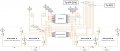
The first image, Circuit Schematic.jpg, is the schematic.
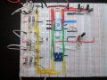
The second image, 4 Circuit Prototype.jpg, is the full view of the bread boarded prototype which corresponds to the schematic.
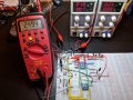
The 3rd image, Circuit 1 - V for Circuit 1 Comparator OUT when Circuit 1 is Closed.jpg, shows V measured on the comparator OUT when the circuit is closed.
The 4th image, Circuit 1 - V for Circuit 1 Comparator OUT when Circuit 1 is Open.jpg, shows V measured on the comparator OUT when the circuit is open.
The comparator here is Analog Devices ADCMP393 which is a quad comparator. I'm supplying the - of each with 42mV, the + of each comes from the high side of a 100 ohm resistor located on the low side of a 1V circuit. Circuit 1, when closed, delivers 500mV to the comparator +. When Circuit 1 is open it delivers 0V to the comparator +. I've verified these measurements for the comparator + and - at multiple points including the actual pins on the comparator.
When closed: + = 500mV, - = 42mV so + > - and comparator OUT should be HIGH
When open: + = 0V, - = 42mV so - > + and comparator OUT should be LOW
Perhaps I've misunderstood or perhaps I've set this up incorrectly?
thx - sean
I have a circuit design and prototype that I'm working on which includes a comparator with open collect/drain outputs and I'm not sure I'm understanding exactly how to employ the pull-up resistor to toggle between HIGH and LOW when the comparator + is above/below the comparator -. I'm attaching my schematic as well as a few images of my prototype which show voltage measurement at the comparator OUT.
The first image, Circuit Schematic.jpg, is the schematic.
The second image, 4 Circuit Prototype.jpg, is the full view of the bread boarded prototype which corresponds to the schematic.
The 3rd image, Circuit 1 - V for Circuit 1 Comparator OUT when Circuit 1 is Closed.jpg, shows V measured on the comparator OUT when the circuit is closed.
The 4th image, Circuit 1 - V for Circuit 1 Comparator OUT when Circuit 1 is Open.jpg, shows V measured on the comparator OUT when the circuit is open.
The comparator here is Analog Devices ADCMP393 which is a quad comparator. I'm supplying the - of each with 42mV, the + of each comes from the high side of a 100 ohm resistor located on the low side of a 1V circuit. Circuit 1, when closed, delivers 500mV to the comparator +. When Circuit 1 is open it delivers 0V to the comparator +. I've verified these measurements for the comparator + and - at multiple points including the actual pins on the comparator.
When closed: + = 500mV, - = 42mV so + > - and comparator OUT should be HIGH
When open: + = 0V, - = 42mV so - > + and comparator OUT should be LOW
Perhaps I've misunderstood or perhaps I've set this up incorrectly?
thx - sean
Attachments
-
 280.6 KB Views: 18
 -
 251.2 KB Views: 17
 -
 260.1 KB Views: 19
 -
 82.7 KB Views: 29


