Facebook
 Google
 GitHub
 Linkedin
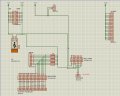
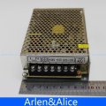
I attached the photo. I calculated the resistance and they are like this:Please post a photo of the power supply connector block showing the labels.
Or a datasheet with the connector pinout.
With the power supply off and disconnected, measure the DC resistance between terminal block pins 5 and 7.
ak
5v - gnd : 50 ohm
12v - gnd : 266 ohm
24v - gnd : 23.72 k
I have 3 power supply, same model, different sellers. They are same
Attachments
-
 158.2 KB Views: 7


")