 Facebook
 Google
 GitHub
 Linkedin
Hello
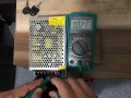
I have a power supply and its model is T50-D, 50W triple power supply, 24V 1A - 12V 1A - 5V 3A, I bought them from AliExpress. When I connect it to RaspberryPi, pi is working normal. But if I connect it to my custom circuit, the current is too high. It is working without problem with powerbanks or 5V adapters like cell phone charging adapters normally.
I checked the power supply pins with a multimeter in diode check mode when the power supply is unplugged and realized there is a shortcut between 12V - 5V and GND pins, 5V is stronger. I have 3 of them and they are all new and giving same result. Should I do something extra to use these PSs? Should I use something like protection diode or something like that? I m not so experienced about power supplies, the answer is simple probably.
I m sharing the picture, any clue can help, thanks.
Attachments
-
 196.1 KB Views: 18
")


