Triggering NE555 with IR sensor

Thread Starter

Starfox

Joined Nov 17, 2018
18
Hello Forum,
I have been trying for a few days now to create this circuit, and I can not get it to work for the life of me.
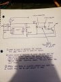
The circuit I am trying to achieve will trip the IR sensor (2-pin IR receiver and transmitter) when an object passes by it, then start a 555 timer.
I want to run a mini-conveyor belt, when the object on the conveyor belt passes past the IR transmitter and reciever, the 555 timer will start.

Currently when I press a momentary switch I can kill the conveyor belt, and have the object sit at a position for a certain time. But since the object is lightweight, I want to be able to trigger the 555 to perform these actions when the IR is blocked (or passed by) with the object (instead of the switch). Does anyone have any idea how to trigger a 555 with a IR Trip?

upload_2018-12-26_19-27-28.png

upload_2018-12-26_19-27-52.png
upload_2018-12-26_19-28-28.png
The highlighted switch is what I want to replace with the IR Trip sensor to detect the object with. With the current circuit configuration, no matter how long the switch is held, the 555 will still only operate for the set time (which is my intention, since the object will be basically sitting, blocking the IR, until the 555 is done).

Thank you to anyone who may have some input! I apologize for any ambiguity. upload_2018-12-26_19-27-28.png upload_2018-12-26_19-27-52.png upload_2018-12-26_19-28-28.png upload_2018-12-26_19-27-28.png upload_2018-12-26_19-27-52.png upload_2018-12-26_19-28-28.png
 

Thread Starter

Starfox

Joined Nov 17, 2018
18
It just needs to provide a negative edge, just like the switch.
Thanks for the quick response! I understand that it just needs a negative edge, but I can't figure out how to build the 2 Pin IR receiver in such a way to achieve that. The IR receiver is "on" until the object hits it, then the object is blocking it "off". But "off" is actually "open" with the 2-Pin IR receiver. I tried using an NPN to sink the trigger-pin to ground when IR receiver is on (then invert the base afterwards in order to make it "Normally On" to "Normally Off") by using it to drive the base of the NPN. But it doesn't seem to be working. I think possibly the power coming from the base of the transistor is not allowing the 555 to actually be shorted to ground.

Any input on how I may be able to configure the "normally on" IR sensor to produce a negative edge? I guess this is where my problem lies. Thank you!
 

Thread Starter

Starfox

Joined Nov 17, 2018
18
What do "on" and "off" mean?
What I men't was: "On", the receiver is conducting and receiving IR light from the transmitter. "Off", the receiver is no longer conducting, the object is blocking the IR light from the transmitter.
 

Thread Starter

Starfox

Joined Nov 17, 2018
18
I am currently trying to pair the IR receiver with an inverter to invert the behavior. (without the 555). The LED is off when the receiver is conducting (as it should) after passing through the inverter. But when I block the IR reciever, the LED does not turn on. If I disconnect the receiver, the LED turns on (since inverted). Do you think I am possibly still receiving very minuscule amounts of IR light even when blocked with a credit card or when they are facing away from each other, and that is why I can't get the inverter input to turn to a low state?
 

dl324

Joined Mar 30, 2015
16,921
Seems like you should be able to use the IR receiver with a resistor connected to the timer trigger. How much current does it source when it's on?

upload_2018-12-26_18-37-33.png
EDIT: Changed timing component values.

Do you have a part number for the sensor?
 

Thread Starter

Starfox

Joined Nov 17, 2018
18
Seems like you should be able to use the IR receiver with a resistor connected to the timer trigger. How much current does it source when it's on?

View attachment 166486
EDIT: Changed timing component values.

Do you have a part number for the sensor?
How much current is sourced from the power supply? I am trying to run the circuit off of a 5V 1A USB brick. Also I can't any real part number, I ordered them on amazon and they are unlabeled. This is the link to the amazon listing: https://www.amazon.ca/dp/B072M6T47C/ref=pe_3034960_236394800_TE_dp_2

It mentions in the description on amazon:
  • Voltage : 2.7~5.5V; Frequence : 38KHz;Operate Distance : 18~20m
  • Bulb Size diameter : 5mm;Peak wavelength (nm): 940nm
  • Item model number: 4331910738
  • 940nm IR Emission :50pcs
    Bulb Size diameter : 5mm
    Pin length: Approx. 25mm / 0.98"
    Operate Distance : 18~20m
    Forward Voltage (V) : 1.2-1.5V
    Peak wavelength (nm): 940nm
    Lens Color : Water Clear
    Material: Semiconductor
    Forward Current: 100mA
    Power: 100mW
    Operating temperature : -25~ +70 ℃
    Storage temperature : -30 ~ +80 ℃

    940nm IR Receiver :50pcs
    Working Voltage : 2.7~5.5V
    Low Level Voltage : 0.40V
    High Level Voltage : 4.8V
    Reception Distance : 18M
    Frequence : 38KHz
    Receiver Angle : ±45°
    Bulb Size diameter : 5mm / 0.2"
    Pin Length : 22.5mm / 0.88"
    Epoxy resin package plus external shielding anti-dry design
    Anti-dry ability, able to withstand the environment dry scratch
    Output match TTL, CMOS level, active low

    I don't know if that helps any, thanks again for all your time!
 

Thread Starter

Starfox

Joined Nov 17, 2018
18
I just modified my breadboard circuit and placed the receiver where you placed it in that diagram as well. It does not seem to be triggering the 555 timer at all. I added an LED into series with the receiver after this observation to check if it was receiving anything, and the led was poorly lit, when it was very close. Don't know if that helps any either. Would be better if I had an oscilloscope. lol..
 

Thread Starter

Starfox

Joined Nov 17, 2018
18
When does the receiver give a LOW and a HIGH?
It seems to give a HIGH when the IR Transmitter and Receiver are able to see each other. They are directly touching each other, after a distance of like 3cm I can't see the LED lit anymore. (Which in my opinion should be much larger of a distance before it shuts off.). So at like 3cm distance I would say it is operating in a LOW state (also when they are not pointed at each other). In either case, the 555 timer is NOT triggered.
 

dl324

Joined Mar 30, 2015
16,921
Then you should be able to connect the receiver output to the trigger capacitor.

If it doesn't trigger, use a larger coupling cap to give a longer trigger pulse. The trigger input needs to go lower than Vcc/3.
 

Thread Starter

Starfox

Joined Nov 17, 2018
18
Then you should be able to connect the receiver output to the trigger capacitor.

If it doesn't trigger, use a larger coupling cap to give a longer trigger pulse. The trigger input needs to go lower than Vcc/3.
You are the man! Thank-you so much! I finally got it to work with that design. I changed the coupling capacitor to 1uF and changed R3 to 1k. It worked!!. And then I placed a NPN between the IR receiver, vcc and the coupling cap (to boost up the range of the signal). My only problem is, originally I had it so that no matter how long the input pulse the timer would start. (I could hold down the button for longer than the 555 output wave) and the 555 would start right as I pressed the button (falling edge 555?). I originally thought that it worked previously due to the diode between the trigger and vcc.

Do you have any suggestions as to how I can make it such that the timer output will go to low even if the IR receiver is still blocked? Because when it is blocked, the timer output remains high forever currently.

Thank you again, i'm very happy to see this starting to work. Thank god its triggering now at least!
 

Thread Starter

Starfox

Joined Nov 17, 2018
18
The input of inverter needs to adds a 10K (or 4.7K) to Ground and that is to pull low the voltage level when the IR doesn't work, you can't left a floating status for an input of any cmos gate.
That is also very good to know, I didn't realize it was a problem! Thanks Scott!
 

Thread Starter

Starfox

Joined Nov 17, 2018
18
You are the man! Thank-you so much! I finally got it to work with that design. I changed the coupling capacitor to 1uF and changed R3 to 1k. It worked!!. And then I placed a NPN between the IR receiver, vcc and the coupling cap (to boost up the range of the signal). My only problem is, originally I had it so that no matter how long the input pulse the timer would start. (I could hold down the button for longer than the 555 output wave) and the 555 would start right as I pressed the button (falling edge 555?). I originally thought that it worked previously due to the diode between the trigger and vcc.

Do you have any suggestions as to how I can make it such that the timer output will go to low even if the IR receiver is still blocked? Because when it is blocked, the timer output remains high forever currently.

Thank you again, i'm very happy to see this starting to work. Thank god its triggering now at least!
So I added a BD139 NPN transistor between the trigger (pin 2) (Emitter) and the coupling capacitor (Collector) with the base not connected. And for some reason I am now able to achieve blocking the sensor, tripping the 555, and allowing the timer to run out (LOW OUTPUT), with the object blocking between the sensor. Which is what I wanted to achieve. Can you guys explain why what I did makes any sense? And if you have any better alternatives let me know! Thanks guys!!
 

dl324

Joined Mar 30, 2015
16,921
So I added a BD139 NPN transistor between the trigger (pin 2) (Emitter) and the coupling capacitor (Collector) with the base not connected. And for some reason I am now able to achieve blocking the sensor, tripping the 555, and allowing the timer to run out (LOW OUTPUT), with the object blocking between the sensor. Which is what I wanted to achieve. Can you guys explain why what I did makes any sense? And if you have any better alternatives let me know!
You shouldn't need a transistor. The receiver output just needs to go lower than Vcc/3.

Please post a schematic.
 

Bernard

Joined Aug 7, 2008
5,784
38 kHz, then emitter should modulated at 38 kHz. For short distance I would use an IR LED & IR transistor with no modulation.
 
Top