Triangular wave form adjustment

Thread Starter

Nomi 1114

Joined Dec 4, 2017
124
Hi, Good afternoon,

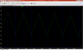
Hope everyone is doing well with good health. Here i would like to ask how can we adjust the triangular waveform offset voltage level. I have designed the ckt for generation of triangular waveform (holding frequency = 70Hz). At the output the shape of wave is good but its start form 1.6V ~ 4.26V (2.7V apx). I need output waveform which starts from zero volts (0V), i am unable to adjust the voltage level. For your reference the screen shots of waveform and schematic diagram is attached. In this regard any body can help me please ( highly appreciated).

Looking forward for your kind reply and prompt response.

I shall be highly grateful to all of you for this act of kindness.


Regards
 

Attachments

Alec_t

Joined Sep 17, 2013
14,313
One way to offset the output voltage as you want is by disconnecting R14 and reducing R9 to 9.1k.
R14 and C7-C10 seem superfluous. What is their intended purpose?
 

Thread Starter

Nomi 1114

Joined Dec 4, 2017
124
One way to offset the output voltage as you want is by disconnecting R14 and reducing R9 to 9.1k.
R14 and C7-C10 seem superfluous. What is their intended purpose?
Dear Respected Alect_t,

Thanks for your kind reply. Secondly i made changes as per your suggestions but the wave shape disturbed. for reference screen shot is attached. before i did the same 10K resistor, after 3 cycles the shape of wave form stable. i need the exactly shape from first cycle, that is possible when R9 is 15K. so any other way ??? by your suggestion offset is zero ... can i refine the top edges of wave form ??

Reagards


1603276274724.png
 

Alec_t

Joined Sep 17, 2013
14,313
With R14 disconnected try R9=14k. That takes the low peak down to about 40mV.
What will you use this triangle wave for? For many applications the waveform shape and absolute peak voltages are non-critical.
 

Thread Starter

Nomi 1114

Joined Dec 4, 2017
124
Here's a simulation for an R11 value of 2.74k.
You could make R11 a pot if you want to get closer to 0V and the bottom peak.

View attachment 220208
Dear Respected crutschow,

First of all thank your very much for your kind help. Secondly still in this simulation i wanna ask two questions as follows;

1. Circuit provide stable output around 50ms, How can i get the stable output from startup.
2. The value of output volatges is about 2.9V, how can i get 4V or above ?

Anxiously waiting for your kind rerply.

With humble regards
 

Thread Starter

Nomi 1114

Joined Dec 4, 2017
124
With R14 disconnected try R9=14k. That takes the low peak down to about 40mV.
What will you use this triangle wave for? For many applications the waveform shape and absolute peak voltages are non-critical.
Dear Respected Alec_t,

Thank your very much for your kind help. Accorind post #7 i can get the exactly shape of the desired waveform, but still 2 qureies are there, as i mentioned in post #8. Need your kind suggestions.

Looking forward for your kind and prompt reply.


Regards
 

Alec_t

Joined Sep 17, 2013
14,313
1. Circuit provide stable output around 50ms, How can i get the stable output from startup.
I don't think you can. Capacitors take time to charge up and power supplies (other than batteries) take time to regulate their outputs.
2. The value of output volatges is about 2.9V, how can i get 4V or above ?
With only 5V as the opamp supply you need an opamp with true rail-to-rail output capability and a lightly-loaded output. The positive feedback of the integrator will need adjustment.
Are you going to tell us why you want such a precise triangle wave?
 

Thread Starter

Nomi 1114

Joined Dec 4, 2017
124
I don't think you can. Capacitors take time to charge up and power supplies (other than batteries) take time to regulate their outputs.

With only 5V as the opamp supply you need an opamp with true rail-to-rail output capability and a lightly-loaded output. The positive feedback of the integrator will need adjustment.
Are you going to tell us why you want such a precise triangle wave?
Dear Respected Alec_t,

Actually further this wave is fed to the circuit of VCO which is used to generate the frequency from 7.7 MHz to 8.7 MHz. I seperately simulate the VCO circuit it works well, but when i combine the VCO part with this ckt, the generated out frequency range disturbed. so i think if we apply the stable triangular wave form containg amplitude 3.5V ~ 4V the may be it works well. Screen shot is attached for your reference please. if you need .asc file then i can also provide for your own analysis.

Looking forward to hear you soon.

Regards
1603423258021.png
 

Thread Starter

Nomi 1114

Joined Dec 4, 2017
124
Dear Respected # crutschow,

I also need valueable suggestions and help on the said agenda as described in post # 11 please.

Waiting for your kind and prompt response please.

Regards
 

eetech00

Joined Jun 8, 2013
3,935
Hello,

Here is an alternate version
Supply is 9v DC.
RF adjusts amplitude
R adjusts frequency
R5/R6 adjusts the output offset

Opamps are Ri-Ro.

I didn't breadboard but it should work.

1603507867899.png

Measurement results:

vout: PP(v(out))=3.93619 FROM 0.05 TO 0.1
out_max: MAX(v(out))=4.07466 FROM 0 TO 0.15
period_out=0.0143579 FROM 0.0642639 TO 0.0786218
freq_out: 1/period_out=69.6479
 

Thread Starter

Nomi 1114

Joined Dec 4, 2017
124
That's difficult with a capacitor used to generate the triangle-wave.

Why do you need it stable from startup?
It doesn't take that long to stabilize in real time.
Dear Respected crutschow,

Thank you very much for your kind help and suggestions. It's really helpful for me. I am really very thankful to you for this act of kindness. But still i need one more help which is posted in next post !!!

Humble regards
 

Thread Starter

Nomi 1114

Joined Dec 4, 2017
124
Hello,

Here is an alternate version
Supply is 9v DC.
RF adjusts amplitude
R adjusts frequency
R5/R6 adjusts the output offset

Opamps are Ri-Ro.

I didn't breadboard but it should work.

View attachment 220449

Measurement results:

vout: PP(v(out))=3.93619 FROM 0.05 TO 0.1
out_max: MAX(v(out))=4.07466 FROM 0 TO 0.15
period_out=0.0143579 FROM 0.0642639 TO 0.0786218
freq_out: 1/period_out=69.6479
Dear Respected eetech00,

Thank you very much for your kind and prompt help. The circuit provided is really very helpful for me. But still i need your help for my last query, which is posted in details in next post.

Thank you very much sir.

with humble regards
 

Thread Starter

Nomi 1114

Joined Dec 4, 2017
124
Dear all,

Hope every one is fine. Here, i would like to ask for help for simulation of my designed circuit. I have designed a circuit for generation of sweep frequency ranging from 7.7MHz ~ 8.7MHz. This circuit consist on two parts (Part -A and Part -B) as mentioned in the attached screenshot. Part-A is used for generation of triangular waveform containing frequency about 170Hz. This signal fed to Part-B which is used as VCO for generation of square wave containing frequency from 7.7MHz to 8.7MHz (A sweep of 1 MHZ). I already simulated this circuit by parts, both parts works well, but when i combined both parts the output frequency disturbed around 13MHz (maybe because of impedance mismatch). And also my laptop become stuck (maybe not good in specifications). So, i need help for simulation of combined circuit and calculate the output frequency sweep, which should be equals to the said frequency band (7.7MHz to 8.7MHz). The output frequency can be adjusted by Rset, Which is connected at the SET pin of LTC1799 (VCO) chip.

For the said purpose (.asc) version of the circuit is attached.

1603559597217.png

looking forward to hear from you soon.


With humble Regards
 

Attachments

atferrari

Joined Jan 6, 2004
4,768
Dear Respected Alect_t,

Thanks for your kind reply. Secondly i made changes as per your suggestions but the wave shape disturbed. for reference screen shot is attached. before i did the same 10K resistor, after 3 cycles the shape of wave form stable. i need the exactly shape from first cycle, that is possible when R9 is 15K. so any other way ??? by your suggestion offset is zero ... can i refine the top edges of wave form ??

Reagards


View attachment 220169
If you are working with op amps, I ask you this: have you any idea of why the top is flat? If yes, do you know how to bring the output to a reasonable level so both peaks are not affected. If so, just do it.

I suspect you are too much behind recipes; why not to work the corrections yourself?

Are all those posters about triangle generation, classmates of the same institute? I can see they are approaching the end of the second pandemic semester.

Could you post verbatim the requirements received from your instructor for this lab?
 
Last edited:

eetech00

Joined Jun 8, 2013
3,935
Dear all,

Hope every one is fine. Here, i would like to ask for help for simulation of my designed circuit. I have designed a circuit for generation of sweep frequency ranging from 7.7MHz ~ 8.7MHz. This circuit consist on two parts (Part -A and Part -B) as mentioned in the attached screenshot. Part-A is used for generation of triangular waveform containing frequency about 170Hz. This signal fed to Part-B which is used as VCO for generation of square wave containing frequency from 7.7MHz to 8.7MHz (A sweep of 1 MHZ). I already simulated this circuit by parts, both parts works well, but when i combined both parts the output frequency disturbed around 13MHz (maybe because of impedance mismatch). And also my laptop become stuck (maybe not good in specifications). So, i need help for simulation of combined circuit and calculate the output frequency sweep, which should be equals to the said frequency band (7.7MHz to 8.7MHz). The output frequency can be adjusted by Rset, Which is connected at the SET pin of LTC1799 (VCO) chip.
Try inserting a non-inverting opamp buffer between part-a and part-b. Isolate the opamp +input from the triangle stage with a 0.1u cap then bias the +input to reduce the dc offset to move the waveform lower peak closer to zero. The buffer should be a rail-rail opamp.
 

Thread Starter

Nomi 1114

Joined Dec 4, 2017
124
If you are working with op amps, I ask you this: have you any idea of why the top is flat? If yes, do you know how to bring the output to a reasonable level so both peaks are not affected. If so, just do it.

I suspect you are too much behind recipes; why not to work the corrections yourself?

Are all those posters about triangle generation, classmates of the same institute? I can see they are approaching the end of the second pandemic semester.

Could you post verbatim the requirements received from your instructor for this lab?
Dear atferrari,

Thank you very much for your kind reply. i am trying to made some modifications and corrections in the ckt as suggested by some other experts. Secondly we all are not classmates and not from the same institute. Honestly speaking i don't know them ..

Regards
 
Top