 Facebook
 Google
 GitHub
 Linkedin
Hello
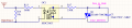
I used the attached circuit for controlling the motor in the gate opener control board. we mass produced this device.
Some customers report Triac failed at the starting moment(about 5 percent). I can't burn Triac in our lab.
I attached my EMI filter too. someone says not placing at the output of line filter can make this problem.
Can anyone help me with this problem?
Attachments
-
 47.6 KB Views: 73
 -
 57.3 KB Views: 70


