 Facebook
 Google
 GitHub
 Linkedin
Hello every one.
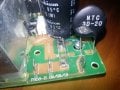
I am hoping to get some advice about a treadmill motor control board which blows the internal 10 amp fuse
as soon as it's turned on. The display console and incline is working but the belt doesn't move when increasing
the speed.
After the first time, I replaced the fuse and it too blew. I checked the board and noticed that the 3 ohm
current limiter(NTC 3D-20) had a crack and it's resistance was 6 ohms. I replaced the fuse and disconnected
the motor and all plugs going out of the board. This time the fuse didn't blow, but the circuit breaker tripped.
The current limiter had a small chunk of casing blown off and the resistance has gone up to 9 ohms. On the
bridge rectifier(KBPC1510) two diodes are fine and two are coming up as shorted.
I decided to desolder the mosfet(IRFP460C) to check it. Unfortunately the desoldering didn't go too well. After
destroying two soldering bits and one hour of leaning over the board, frustration got the better of me and the
board recieved a whack with pliers, with the intention of rendering it unserviceable, and leaving me free to move
on. Just for good measure I also gave the rectifier(F10u60DN) a tug as well. After a visual inspection, there doesn't
seem to be any physical damage. I am resigned to having to throw it away but couldn't without giving it one
more try.
What I would like to ask is:
1. The mosfet is obsolete. Which properties are the most important to consider for the replacement?
2. Would 2.5 ohms or 4 ohms be ok for the current limiter or does it have to be 3 ohms. Having trouble locating 3 ohms?
3. According to listings on amazon the bridge rectifier is half wave. Is this the reason two diodes on the board are showing as
shorted and there is nothing wrong with it?
Thank you for reading.
P.S.
It would rightly appear to some as an overreaction on my part to a failed desoldering attempt. The failure to remove the mosfet
was just the last straw. Electronics has been a love of mine since the age of ten. Now in my early forties and after countless
hours spent in libraries, lots of money spent on buying books and all those hours on Youtube has not resulted in much understanding
of the subject. I can tell from experience that not understanding something you like is very frustrating.
Sorry for the long post.
Attachments
-
 159 KB Views: 77
 -
 50.2 KB Views: 86
 -
 57.8 KB Views: 74
 -
 159 KB Views: 76
 -
 50.2 KB Views: 72
 -
 57.8 KB Views: 64


