Transistors

Thread Starter

anditechnovire

Joined Dec 24, 2019
105
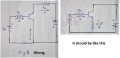
Why is the input mode different in some" common collector "mode of a transistor circuit diagram? Some are between the emitter-base while others are between the collector- base. Will they not have different effects?
 

Papabravo

Joined Feb 24, 2006
21,159
There are three configurations of the transistor and they each have different properties. They are referred to by the names:
  1. Common Emitter
  2. Common Base
  3. Common Collector, aka Emitter Follower
These names and the circuits they represent were derived from similar circuits and names from the vacuum tube era. They were:
  1. Common Cathode
  2. Common Grid
  3. Common Plate aka Cathode Follower
 

Thread Starter

anditechnovire

Joined Dec 24, 2019
105
No.
I don't know what "between the collector-base" means.
Ok I mean that in some diagram s of an emitter follower(CC mode), the input voltage is applied in between the collector and base junction, while in other schematic, it's applied inbetween emitter and base
 

Papabravo

Joined Feb 24, 2006
21,159
Ok. I mean that in some diagrams of an emitter follower(CC mode), the input voltage is applied in between the collector and base junction, while in other schematic, it's applied in between emitter and base N.B. this would be a common emitter configuration.
That is because different circuits do different things. It would help greatly if you showed us a picture of what you are talking about. Words just do not suffice.
 

dl324

Joined Mar 30, 2015
16,845
Ok I mean that in some diagram s of an emitter follower(CC mode), the input voltage is applied in between the collector and base junction, while in other schematic, it's applied inbetween emitter and base
We need to see a schematic. It's possible to operate a transistor in inverted mode, but you have a very low beta.
 
Last edited:

Bordodynov

Joined May 20, 2015
3,177
What do you say to my example of two circuitry? The upper one is a circuit with a common collector, and the lower one is a circuit with a common emitter. I counted the voltage swings on the output resistor.:)
 

Attachments

Thread Starter

anditechnovire

Joined Dec 24, 2019
105
Welcome to AAC!

It would be helpful if you posted circuits so we can see what you're talking about.
We need to see a schematic. It's possible to operate a transistor in inverted mode, but you have a very low beta.

Welcome to AAC!

It would be helpful if you posted circuits so we can see what you're talking about.
9
Like to see that.

ak
 

Attachments

Wolframore

Joined Jan 21, 2019
2,609
Actually I ran the simulation its interesting. fig 2 is better than fig 1... there less drop on the base resistor increasing base current about 100x more and causing the transistor to saturate. It’s unusual and not normally done this way but I like it.

note simple sim performed using same transistor, all resistors as 1k and same voltage sources. But theres A huge difference between the two which is. 1st one has one voltage source and second has 2 separate sources. Edit using 1v sources when I raise the voltages it just gets about double current you have to lower load to see it. Makes sense with double voltage but very interesting when it’s 1v sources... greater delta due to ratio of Vfd to bias voltage.
 
Last edited:
Top