Transistors, why is it here saturated ?

Thread Starter

Xenon02

Joined Feb 24, 2021
504
This is why you need to forget about Ic_max. You need to back to basics and stop using the "shortcuts" (Ic_max).
Transition enters saturation region when Vc < Vb.


View attachment 274939

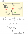
Can you solve for Ib, Ic, and Vce? And determine whether the BJT is working in the active region or in the saturation region.
Assume Vbe = 0.7 and β = 100.
1661705769812.png

So I guess the second one is in saturation. And what can I do with it now ?
Should I calculate what is the Vce ?

Also what should I do with Re if I add there. And why did we focus on Ic_max before ? I remember that I used Ic_max many times, so it's something new that I'm not using it.
 

Thread Starter

Xenon02

Joined Feb 24, 2021
504
Oh not again :(

I just ignored the Ic_max like jony mentioned.
So I calculated the Ic which was 24 mA. And the same current flows through Rc.

By the way what TS is a short of ? I thought that I will read X2 is acting as a Troll :D
 

Thread Starter

Xenon02

Joined Feb 24, 2021
504
I hope that you know that 24V across Rc is impossible in the circuit supply from 12V. So in reality transistor will be saturated. And Vce will be around 0.2V or less, thus the Rc voltage drop is around 11.8V.
Okey, so with Re how should I calculate it ? Because it won't be that easy Vb can change.
Also is there a way to calculate the range ? Like you did for which value it saturates without the pattern of Ic_max ?
 

Jony130

Joined Feb 17, 2009
5,598
Also is there a way to calculate the range ? Like you did for which value it saturates without the pattern of Ic_max ?
Sure, look at this example
untitledaa.PNG

I hope that you see that Ve = 1V and Ie = 1V/1kΩ ≈ 1mA.
So what allowed voltage range do we have for V_RC before the transistor enters the saturation?
 

ericgibbs

Joined Jan 29, 2010
21,448
Hi,
As this is in the Homework Forum, helpers should only give hints and clues to help the TS's to work out the solution themselves, not to post answers.

Moderation
 

WBahn

Joined Mar 31, 2012
32,878
View attachment 274895

I know that Vbe = 0,7V. but I couldn't get the information about UR and UE. but it somehow saturated even though the current on collector circuit isn't maximum ? Ic_max =5V/1k = 5mA ?
When you say that Ic_max is 5 mA, you are abusing Ohm's Law because you are grabbing the nearest voltage and resistance and throwing them at a formula.

Ic_max is determined by the maximum voltage that can appear across Rc (the collector resistor) -- and that is NOT 5 V.

As you go from the 5 V rail down to the 0 V rail, your voltage drops across not only Rc, but also across Vce and across Re (the 40 Ω emitter resistor).

On your diagram you have a notation that beta is 100. But if it is in saturation, then that is not the case.

There are a few ways to go about this. Given this circuit, figure out first what Ve (the emitter voltage) is going to be, at least approximately.

If we, as a first estimate, ignore the base current then the base voltage will be 2.5 V and the current in the bias resistors will be 3.125 mA. The emitter voltage will be about 1.8 V yielding an emitter current of 45 mA.

Where is this current coming from? Let's, for the moment, assume that the transistor is NOT saturated and assume that your beta=100 value is good. That means that about 0.45 mA is coming from the base (which is a noticeable fraction of the bias current) and the other 44.6 mA is coming from the collector via the collector resistor. But that then means that the collector resistor has a 44.6 V drop across it. So clearly the transistor is NOT in the active region.

So let's go the other way and assume that the transistor is in deep saturation such that the voltage across Vce is Vcesat, or about 0.2 V for most small signal silicon transistors. Still assuming that the base current is negligible compared to the bias current (and this is looking like a very poor assumption), with an emitter voltage of 1.8 V and Vcesat of 0.2 V, the collector voltage will be about 2.0 V, meaning that only 3 mA can flow through Rc and that the remaining 42 mA of the emitter current has to be coming from the base. But that is WAY more than the total current flowing into the bias network. So the assumption of negligible base current is a horrible one.

So let's keep only two assumptions -- that Vbe is 0.7 V and that Vce is Vcesat. The first one is pretty shaky with these kinds of base currents, but without a specific diode part number we can't do much better.

As you can see from the annotated diagram, we have eight unknowns (five currents and three voltages). But we only have three meshes, so let's use mesh current analysis.

fig1.png
 

Thread Starter

Xenon02

Joined Feb 24, 2021
504
Sure, look at this example
View attachment 274947

I hope that you see that Ve = 1V and Ie = 1V/1kΩ ≈ 1mA.
So what allowed voltage range do we have for V_RC before the transistor enters the saturation?
Hmm according to this, and knowing that Vce_sat = 0,2V. So Ve must be 1V no matter what.
12 V - 0,2V - 1V = 10,8V is a maximal V_RC ? or a little bit smaller is a maximal voltage on Rc. The voltage on Vce will be 0,2V constant or something like that and Ib = Ic*B won't work.

But I meant what if I had Rb, Re and Rc. voltage on Vb changes. Vc also changes so it's hard to determine.
 

WBahn

Joined Mar 31, 2012
32,878
I just ignored the Ic_max like jony mentioned.
So I calculated the Ic which was 24 mA. And the same current flows through Rc.
When working with diodes and transistors and other components that have different operating regimes (e.g., cutoff, active, saturation), your analysis generally assumes that you are in one of the regimes. Once you get your results, you then need to confirm whether or not those results are consistent with that assumption.

In this case, you assumed that you are operating in the active regime and got Ic = 24 mA. But is that consistent with being in the active regime? No, because that would place the collector of the transistor at -12 V. So you know that it is NOT in the active regime. This means that your results are, in part or in whole, wrong because you made a wrong assumption. As you identified, it is in the saturation regime. So now you have to redo the analysis applying the assumption that you are in the saturation regime. What do you get for Vc and Ic under that assumption?
 

Thread Starter

Xenon02

Joined Feb 24, 2021
504
By the way from my first post.
Why do I have to assume that voltage on resistor is 2,5V ? And if it changes to 1,9 V then the transistor is in saturation ?

When I have a resistor with Rb then the voltage on Vb changes and it can be in active mode.


The rule is always the same.
The same ?
The only assumptions I can make is that Vce = 0,2V and Vbe = 0,7V.
I see that the mesh current analisys is an option but is it possible using KVL and KCL? Or other methods ?


What do you get for Vc and Ic under that assumption?
I am not sure. I know that Vce = 0,2V so maybe Vc has a low value?
 

Jony130

Joined Feb 17, 2009
5,598
but is it possible using KVL and KCL?
Sure, you can use it.
Why do I have to assume that voltage on resistor is 2,5V
Voltage divider

5V * 800Ω/(800Ω + 800Ω) = 2.5V And because the resistor used in the divider are "small", we have a "stiff" divider. Thus, the loading effect by the base current won't change the divider output voltage much.

And if it changes to 1,9 V then the transistor is in saturation ?
Smoller voltage at the base means that the Re will also see a smaller voltage. Thus, Ie current will drop too. So, for an unchanged RC value, the voltage drop across RC resistor drops too.
So, we are moving away from saturation.
 

WBahn

Joined Mar 31, 2012
32,878
By the way from my first post.
Why do I have to assume that voltage on resistor is 2,5V ? And if it changes to 1,9 V then the transistor is in saturation ?
You don't have to. This is a common assumption because designers of circuits often design the bias network such that the base current is negligible compared to the other currents. So, in this case, if the base current is small compared to the current in the top 800 Ω resistor, then the current in the bottom 800 Ω resistor would be very close to the same amount and, hence, they would act as a classic voltage divider yielding a base voltage of 2.5 V.

So a first pass analysis is to see if this assumption is reasonable. In this case, it is not even close to reasonable because the emitter current ended up being 45 mA and the collector can only supply about 3 mA of that. So the base current is well over 40 mA. But the current in R1, assuming Vb is 2.5 V, would only be a little over 3 mA. So the assumption that the base current is a negligible fraction of the bias network current is a bad one and we have to start over and avoid making that assumption.

I see that the mesh current analisys is an option but is it possible using KVL and KCL? Or other methods ?
You can use any legitimate technique. You have eight equations and eight unknowns. Solve them however you like.

Remember, mesh current analysis is nothing more that a formalized way of applying KVL such that KCL is guaranteed to be satisfied, while node voltage analysis is nothing more than a formalized way of applying KCL in such a way that KVL is guaranteed to be satisfied.

I am not sure. I know that Vce = 0,2V so maybe Vc has a low value?
What low value?

What is Ve in that circuit?

If you know Ve and you know Vce, what is Vc?
 

crutschow

Joined Mar 14, 2008
38,526
What you seem to have a problem with, is any kind of intuitive feel for Ohm's law and how it works, even though you say you understand it, so you blindly keep asking questions where the answers should be obvious from the other answers we have given you, and we thus keep going in circles.
That's why your questions seem like you are trolling us.
And unfortunately I don't think intuition is something we can help you get. :(
 

WBahn

Joined Mar 31, 2012
32,878
Sure, you can use it.

Voltage divider

5V * 800Ω/(800Ω + 800Ω) = 2.5V And because the resistor used in the divider are "small", we have a "stiff" divider. Thus, the loading effect by the base current won't change the divider output voltage much.
On what basis is 800 Ω being considered "small" enough to make the divider "stiff"?

For this circuit, this turns out to be a HORRIBLE assumption.

The divider network will be stiff ONLY if the base current turns out to be a small fraction of the current entering the bias network. This is usually taken to be less than 1%, but less than 10% is often accepted.

Whenever you make an assumption, you really need to verify that that assumption was actually reasonable.
 

Jony130

Joined Feb 17, 2009
5,598
On what basis is 800 Ω being considered "small" enough to make the divider "stiff"?

For this circuit, this turns out to be a HORRIBLE assumption.
Assumed Ie = 45mA and the "real" one is Ie = (2.5V - 0.7V)/(40Ω + 400Ω/101) ≈ 40.9mA. For me personally, this is not a HORRIBLE assumption. But I understood your point here.
 
Top