Transistor will not shut off

t_n_k

Joined Mar 6, 2009
5,455
Hi Ron,

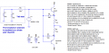
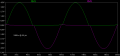
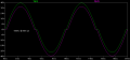
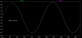
A value of 3nF seems remarkable. Certainly if I include this value across the B-E junctions I see the 'problem' as well in a simulation at 60kHz. I also see the 'expected' behavior at 100Hz with the same schematic (other than using a much bigger source coupling capacitor).

If that's the issue, which seems most likely with all other options fast vanishing, then well done on your part. :)

EDIT: Perhaps a Cje of 3nF isn't all that remarkable. I note from another source an MJE2955 for instance has a typical Cje of 390pF.
 
Last edited:

CDRIVE

Joined Jul 1, 2008
2,219
You think you eliminated capacitance as the problem, but you have underestimated the base-emitter capacitance of these transistors. <snip>
Ron, that was a great job of sleuthing!;) When I modeled hensle's circuit I used generic transistor models that had Cbe no where near those values. It's no wonder the issue didn't show itself in my sims.

This is a good point Ron,
I thought a buffer was provided by the emitter follower. If this circuit had worked, I was going to cascade the emitter followers, each one allowing more current while not causing the voltage to drop (too much) at the oscillator.

However, this does not seem to work. No matter how many emitter followers I use, when the final one's resistance gets too low, the oscillator fails.

Do you know a good method to isolate the oscillator? Is it possible?
Emitter Followers are supposed to be a good choice for providing a High Z input while delivering power to a Low Z load. The problem is these attributes are being negated by the very high Cbe of your transistors.
 

Ron H

Joined Apr 14, 2005
7,063
This is a good point Ron,

I thought a buffer was provided by the emitter follower. If this circuit had worked, I was going to cascade the emitter followers, each one allowing more current while not causing the voltage to drop (too much) at the oscillator.

However, this does not seem to work. No matter how many emitter followers I use, when the final one's resistance gets too low, the oscillator fails.

Do you know a good method to isolate the oscillator? Is it possible?
I don't think you ever answered this question:
What is the inductance of your inductor?
 

Thread Starter

hensle

Joined Dec 31, 2011
46
You think you eliminated capacitance as the problem, but you have underestimated the base-emitter capacitance of these transistors. They are not spec'ed, but the spice models have Cje on the order of 3nF for both of them. This makes the capacitive reactance on the order of 1kΩ at 60kHz, which is 10% of the value of your emitter resistors. Try testing at 100Hz (you may have to use a larger input capacitor, or just direct-couple the input signal). At low voltages, you will see the half wave rectification you are looking for. At higher voltages, look closely, and you will see what looks like crossover distortion, due to base-emitter breakdown. I ran some sims and saw exactly what you did at 60kHz, and saw what I am predicting you will see at 100Hz (I added Veb breakdown diodes in parallel with the BE junctions, because the model does not include Veb breakdown).
Thank you for your great work on this. Your prediction came true in real life.

I replaced my oscillator with a function generator and started at 100Hz to see the progression of this capacitance issue. I think there could be further discussion, because I am still puzzled by aspects of it.

I ran the test on each of the 4 sets of transistors. These are the results:

transistor/trans freq./case type/start of shutoff failure/no shutoff at all
TIP48G/10MHz/TO-220/1.4kHz/135kHz
NTE2517/30MHz/TO-126/4.8kHz/133kHz
MPS3704/20MHz/TO-92/28kHz/417kHz
TIP31C/2MHz/TO-220/800Hz/100kHz

Here is the question.

With the capacitance becoming an issue at such low frequency, how can any class B amplifier work?

Even audio amplifiers should work up to 20kHz at which all but one of these transistors degrades.

And what about amplifying radio frequencies? None of these transistors would work.

What point is the transition frequency as none of the transistors even come close to working at that point. The NTE transistor is stated to be specifically designed for radio frequency amplification, but I don't see how.

???????

Let me clarify this last statement. I chose the TIP48G because its transition frequency was 10MHz. That meant that at 900kHz the transistor should still amplify. In the datasheet they even tested some of the values at 1MHz, so I thought I had the right transistor for the job. Now it appears that it fails to function at any frequency above 1.4kHz.....is that the case?
 
Last edited:

t_n_k

Joined Mar 6, 2009
5,455
Here is the question.

With the capacitance becoming an issue at such low frequency, how can any class B amplifier work?

Even audio amplifiers should work up to 20kHz at which all but one of these transistors degrades.
Perhaps it has something to do with the topology you adopted. Crutschow commented on this in post #14.
 

Ron H

Joined Apr 14, 2005
7,063
Thank you for your great work on this. Your prediction came true in real life.

I replaced my oscillator with a function generator and started at 100Hz to see the progression of this capacitance issue. I think there could be further discussion, because I am still puzzled by aspects of it.

I ran the test on each of the 4 sets of transistors. These are the results:

transistor/trans freq./case type/start of shutoff failure/no shutoff at all
TIP48G/10MHz/TO-220/1.4kHz/135kHz
NTE2517/30MHz/TO-126/4.8kHz/133kHz
MPS3704/20MHz/TO-92/28kHz/417kHz
TIP31C/2MHz/TO-220/800Hz/100kHz

Here is the question.

With the capacitance becoming an issue at such low frequency, how can any class B amplifier work?

Even audio amplifiers should work up to 20kHz at which all but one of these transistors degrades.

And what about amplifying radio frequencies? None of these transistors would work.

What point is the transition frequency as none of the transistors even come close to working at that point. The NTE transistor is stated to be specifically designed for radio frequency amplification, but I don't see how.

???????

Let me clarify this last statement. I chose the TIP48G because its transition frequency was 10MHz. That meant that at 900kHz the transistor should still amplify. In the datasheet they even tested some of the values at 1MHz, so I thought I had the right transistor for the job. Now it appears that it fails to function at any frequency above 1.4kHz.....is that the case?
CAVEAT: The following comments are based on simulation.
If you get rid of the 10k emitter resistors, tie the resistors together, and instead drive, say, a 40 ohm load, the resulting class B amplifier looks pretty good at 60kHz, if you drive it with a voltage source. It even works at 900kHz if you have the drive capability.

14.5uH is about 80 ohms at 900kHz. You would have to put almost 300V p-p across it to get ±1.8 Amps.
 

Thread Starter

hensle

Joined Dec 31, 2011
46
CAVEAT: The following comments are based on simulation.
If you get rid of the 10k emitter resistors, tie the resistors together, and instead drive, say, a 40 ohm load, the resulting class B amplifier looks pretty good at 60kHz, if you drive it with a voltage source. It even works at 900kHz if you have the drive capability.
I am glad I posted here. Ron, thanks, you have given me great help on this. I would also like to thank the others who contributed. With this input, it gives me some direction to take this project and also gives me some hope that I can get it to work.

14.5uH is about 80 ohms at 900kHz. You would have to put almost 300V p-p across it to get ±1.8 Amps.
Oops. I gave the inductance of the inductor in the oscilator. The inductance of the load is 8.8uH. Though still I probably won't get 1.8A. But if I could get 1A to work, it would be a good start. I could then tweak it from there. (e.g. add some capacitance to reduce the inductive reactance)
 

Ron H

Joined Apr 14, 2005
7,063
To follow up on the class B Vbe breakdown that you were concerned about:
With a class B push-pull emitter follower, the emitter of the OFF transistor is bootstrapped to its base by the emitter of the ON transistor, and was therefore only reverse biased by the amount of the fwd Vbe drop of the ON transistor (≈0.7V to 1V). Your circuit had independent emitters, each with a resistor to GND. This meant that the emitter was at 0V when the base went below GND (NPN), so the base-emitter junction would break down if the base went below 5V (spec value).

EDIT: What is the series resistance of your 8.8uH inductor?
 
Last edited:

Thread Starter

hensle

Joined Dec 31, 2011
46
To follow up on the class B Vbe breakdown that you were concerned about:
With a class B push-pull emitter follower, the emitter of the OFF transistor is bootstrapped to its base by the emitter of the ON transistor, and was therefore only reverse biased by the amount of the fwd Vbe drop of the ON transistor (≈0.7V to 1V). Your circuit had independent emitters, each with a resistor to GND. This meant that the emitter was at 0V when the base went below GND (NPN), so the base-emitter junction would break down if the base went below 5V (spec value).
OK. I was wondering. Great.

EDIT: What is the series resistance of your 8.8uH inductor?
Less than an ohm. It is a handwound air coil of about 70 winds. There is actually a secondary so there will be a back emf. But it is weakly coupled so not much. In a simulation it was a couple volts.
 

Ron H

Joined Apr 14, 2005
7,063
OK. I was wondering. Great.


Less than an ohm. It is a handwound air coil of about 70 winds. There is actually a secondary so there will be a back emf. But it is weakly coupled so not much. In a simulation it was a couple volts.
What is the magic in 900kHz? Does it have to be exactly 900kHz?
 

CDRIVE

Joined Jul 1, 2008
2,219
Less than an ohm. It is a handwound air coil of about 70 winds. There is actually a secondary so there will be a back emf. But it is weakly coupled so not much. In a simulation it was a couple volts.
What does this mean? An inductor will exhibit back emf regardless of a secondary or not. In fact, the tighter the coupling and higher the power transfer into a resistive load, the less the back emf on the primary will be.
What is the device your trying to build?
 
Top