Transistor Tester (PW July & August 1976)

Thread Starter

brianmk

Joined Dec 23, 2016
102
I have just re-read the last sentence of the operating instructions when measuring diodes.

It says:-
"Germanium diodes will read approx two-thirds full scale, whilst, due to their higher forward voltage, silicon diodes will read approx half full scale."

Germanium diodes give a higher meter reading than silicon diodes.
This means the meter reading cannot be directly proportional to the forward diode voltage.
My earlier thought that the diode forward voltage is represented by the difference between the actual meter reading and full scale appears to be correct. The meter readings are reversed.

I am not yet sure how this affects things when trying to measure LED forward voltages.
 

Thread Starter

brianmk

Joined Dec 23, 2016
102
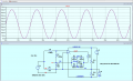
It appears to work reasonably well for LEDs:-
S3 needs to be set to the 10mA range.
Vc needs to be set to around 3.37V to give FSD with the LED shorted.
With the short removed, the current through the LED is around 6.5mA.
The current through the 100uA meter is 65uA. 100-65 = 35uA. That equates to a forward voltage of 3.5V.
The simulation gives a voltage of about 3V for a randomly picked NSPW500BS device.
The error is about 16%.


1734880919637.png
 

ericgibbs

Joined Jan 29, 2010
21,488
It differs from the original in that my analogue meter is 100uA instead of 500uA.
Hence R30 is 1K instead of 200R.
hi b,
I guess you realise that as the OPA minimum fixed feedback resistor is in the order of 1.2meg Ohms that using a 100uA meter in place of a 500uA meter and attempting to compensate by changing the equivalent resistor from 200R to 1k will not reduce the meter current from 500uA to 100uA.?

Using a simplified version of the two options, shows that changing the 200R, 500uA meter to a 1k, 100uA meter requires a shunt of 250R

E
EG57_ 2477.png
 

Attachments

Thread Starter

brianmk

Joined Dec 23, 2016
102
Do you mean the maximum is 1.2Meg?
Is that just a simulation issue when using a generic op amp model?
The input impedance of a CA3130 is 1.5 TOhms and the input current around 5pA.

I tried changing the resistor (R30 in the original schematic) from 1K to 200 in my 100uA meter simulation using a LED for the DUT.
That simulation also uses a generic op amp model ('UniversalOpAmp').
The meter current changed from 68.88uA to 344.16uA. 344.16/5 = 68.83.
So I don't see a problem. Am I missing something?

Incidentally, the 100uA meter I am using has an internal resistance of 1.43K although that makes little difference when used in a feeback loop.
 
Last edited:

ericgibbs

Joined Jan 29, 2010
21,488
Hi,
Original circuit ref.
R31 [1k] > Meter [1k} > R29 [1.2meg] are the minimum feedback resistor chain value.
So the inverting Gain is G = Rfb/Rin.

Note on this image Vx and Vy are at the same voltage, so that the current through the Non Inv input 1.2meg cancels the current on the Non Inv input of the OPA.

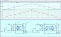
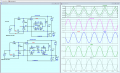
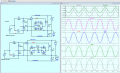
1st image, Check Vout1 and Vout2, note the Offset.
Both meters show 500uA.

2nd image. with a 250R shunt resistor, the 100uA meter shows 100uA FSD


The point I am querying is the very small effect on the gain changing the Rmtr from 200R to 1k will have on the gain, when using a 100uA mtr in place of a 500uA mtr.

This LTS sim that just shows the basic OPA circuit.
EEG57_ 2478.pngEG57_ 2479.png
 

Attachments

Last edited:

Thread Starter

brianmk

Joined Dec 23, 2016
102
As far as I can see, the difference in offset between Vout1 and Vout2 is down to schottky vs silicon diodes rather than the difference in meter resistance between 500uA and 100uA meters.
If you change BAT54 to IN914 in both circuits then they both behave the same.
 

ericgibbs

Joined Jan 29, 2010
21,488
hi b,

That is the point I'm making, the gain of the OPA is set by the Vx , Vy voltages [ note they are the same voltage for both meter set-ups] via that 1.2meg to the OPA Inv Input.
So it will force a 500uA current the meter feedback loop, at full scale for both types of meter.

Try a 250R shunt across the 100uA meter.

E
 

Thread Starter

brianmk

Joined Dec 23, 2016
102
Yes - that is exactly what I have done in my version of the circuit!
If you look at the all the simulations I have uploaded (with a 100uA meter), they all use 1K for R30 in place of the original 200 Ohms.

My version of the tester also includes an 'Icx10' meter setting. It reduces the gain by a factor of 10 by switching another 9K in series with R30 giving a total of 10K. That allows for testing transistor HFE at collector currents up to 300mA.
 

Thread Starter

brianmk

Joined Dec 23, 2016
102
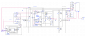
I'm not sure if it will be readable on here but my version of the schematic in DesignSpark looks like this:-

Unfortunately DesignSpark only allows exporting as a '.bmp' format file which is not really readable. There is no PDF export option.

1735043103805.png
 
Last edited:
Top