Facebook
 Google
 GitHub
 Linkedin
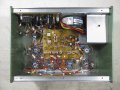
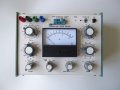
A while ago, I built a modified version of an old school Transistor Tester described in PW July and August 1976.
The design is almost 50 years old but it works as expected when measuring bipolar transistor HFE.
According to the description, it can also be used measure diode forward and reverse characteristics:-

This makes no sense to me at all!
Can anyone enlighten me?
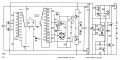
I have attached the schematic of the original design.
The design is almost 50 years old but it works as expected when measuring bipolar transistor HFE.
According to the description, it can also be used measure diode forward and reverse characteristics:-
This makes no sense to me at all!
Can anyone enlighten me?
I have attached the schematic of the original design.
Attachments
-
 2.1 MB Views: 54

")