Transistor Tester (PW July & August 1976)

Thread Starter

brianmk

Joined Dec 23, 2016
102
There is clearly a misunderstanding here.
The 'applied' voltage across the diode is irrelevant. There is no fixed voltage.

The tester feeds a fixed current through the diode.
When passing that current, I can measure the voltage across the diode using a DMM. I measure 0.65V.
When the tester measures the same voltage using the same current it gives 0.44V.
That has to mean that either the tester is not measuring the voltage correctly or the DMM is faulty.
Right now I trust the Fluke result rather than a home made, untried tester.
 

ericgibbs

Joined Jan 29, 2010
21,487
hi,
It is possible that we have a misunderstanding.

To recap, when the diode is inserted into your tester, your DVM measures 0.65Vfwd
but the tester indicates 0.44Vfwd.
I would agree the Fluke reading would be accurate.

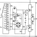
I will relook at your initial diagram, it suggests the current to voltage conversion is at fault.
Is that section of the diagram the same as posted, no mods?

E

BTW: which setting do you have the S3 set too.?

Also VR2 setting, which sets the I2V OPA gain/offset


Added:
Clip of the I2V section.
EG57_ 2440.png
 
Last edited:

Thread Starter

brianmk

Joined Dec 23, 2016
102
Let's simplify things.
To remove any potential misunderstandings about non-linear devices, I will use a 1K resistor in place of a diode.
First I short the A & K terminals and adjust Vc to give full scale on the internal meter.
Then I replace the short with a 1K resistor.
The internal meter now reads 0.48V.
The Fluke DMM reads 0.52V.
 

ericgibbs

Joined Jan 29, 2010
21,487
hi,
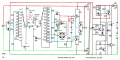
I assume the circuit is as per this diagram and also the components being used.

What are the settings on the S1 and S3 selector switches?


E
 

Attachments

Last edited:

Thread Starter

brianmk

Joined Dec 23, 2016
102
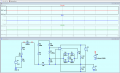
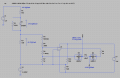
Here is an LTSpice model.
It differs from the original in that my analogue meter is 100uA instead of 500uA.
Hence R30 is 1K instead of 200R.
The meter diodes are Schottky devices.
There is also a 1N4148 protection diode in parallel with the meter - although that makes virtually no difference.
The DUT is a 1N4004.
I also use +/- 6V rails for the op amp.
I was unable to find a model for the CA3130 so it's a generic op amp.

Using the model...
First I shorted the DUT and adjusted V1 to give FSD (100uA) through the meter.
This requires V1 to be set to 11.048V.
Then I removed the short and measured the meter current. It measures 42.8uA indicating the voltage drop across the DUT to be 0.428V.
However if I measure the actual voltage across the DUT in the model, it indicates 0.544V.

The discrepancy agrees fairly well with what I measure using the real circuit.

I did wonder if the analogue meter I am using contributes some non-linearity errors (especially at FSD) but the results using the LTSpice model suggest that's not the problem.
 

Attachments

Last edited:

Thread Starter

brianmk

Joined Dec 23, 2016
102
If I replace the DUT in the model with a 1K resistor, the current through the meter indicates 48.8uA (equivalent to a measured voltage of 0.488V).
The voltage across the 1K resistor in the model is 0.487V.
 

ericgibbs

Joined Jan 29, 2010
21,487
Hi,
I have just created a CA3130 LTS model, and also creating the circuit.

Unzip this, its not pretty but it works.
Put the sub file in your lib folder
Put the asy file in your Autogen folder.

Ask if you have a problem
E
EG57_ 2446.png
 

Attachments

Thread Starter

brianmk

Joined Dec 23, 2016
102
I don't think it needs an accurate CA3130 model for this. Any op amp model will do as long as it has a high input impedance.

I am begining to think there is something fundamentally wrong with the way the diode forward voltage is being measured using this setup. I just haven't managed to get my head around it yet.
 

ericgibbs

Joined Jan 29, 2010
21,487
hi,
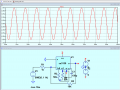
Check this simplified circuit for any error, correct any you find and repost.

Interestingly, this diode Vfwd is the same as the DVM???

E

EDIT: please show how you have connected the +/-6V for the OPA supply,

EG57_ 2449.png
 
Last edited:

Thread Starter

brianmk

Joined Dec 23, 2016
102
Perhaps I made a wrong assumption in the switching arrangements when measuring diode 'If'.
I thought that when S2 is in position 2 (Ices,Ir) then S1 is always left in position 1 (Ices).
The diode current is then fixed as defined by R13 (820 ohms).
Your simulation shows an 18V power rail. This should be 12V. (In the original design, the 18V battery is regulated down to 12V).
It probably make little difference to the problem in hand.

Your diagram shows S1 in position 11 (3mA) and S1 can be used to vary the diode forward current.
However the current settings marked on the switch will be incorrect since they are relative to 0V (i.e. TUT Emitter).

Note that the original documentation only talks about adjusting Vc using VR3 when measuring diodes.
It makes no mention of making adjustments to VR1.
To me that suggests that S1 should be left in the Ices position such that VR1 makes no difference.
If this is the case then the simulation needs to include R13 (820 Ohms) + R14 (33 Ohms) connected to the 12V rail.
R1 and R2 are not connected and are irrelevant when measuring diodes.

In my case I have used S1 positions 1 and 12 to allow higher currents (30mA and 100mA) to be selected.
Iceo and Ices have been moved onto another wafer switch along with If.
Currently I don't have the option of adjusting the current via S1 when 'If' is selected.

I may need to rethink my switching arrangement.
Luckily the Iceo position on my wafer switch is not really necessary since I have an additional momentary 'Test' push button that connects S1 wiper to the TUT/DUT. Not pressing the button has the same effect.
Hopefully, if I have got things wrong, I can reuse the Iceo position to connect S1 wiper to the DUT when measuring If.
 
Last edited:

panic mode

Joined Oct 10, 2011
5,099
"Conduction in the forward direction is checked at Position IF of the IR/IF switch."

That tells me that S2 must be in the upper position.
That means s2a connect to IF and same goes for S2b. for that S1 need to be in Ices position and S3 position does not matter.

the current then flows through R13, R14, DUT, etc.
 

Thread Starter

brianmk

Joined Dec 23, 2016
102
hi,
Check this simplified circuit for any error, correct any you find and repost.

Interestingly, this diode Vfwd is the same as the DVM???

E

EDIT: please show how you have connected the +/-6V for the OPA supply,

View attachment 338427
"Conduction in the forward direction is checked at Position IF of the IR/IF switch."

That tells me that S2 must be in the upper position.
That means s2a connect to IF and same goes for S2b. for that S1 need to be in Ices position and S3 position does not matter.

the current then flows through R13, R14, DUT, etc.
I agree with 'panic mode'. That was my assumption too. If this is the case then the LTSpice simulation schematic above is incorrect.
Also the schematic above does not include the current chain resistors R16-R23 (99900 Ohms) in series with R28 (200K). They should connect between the op amp inverting input and the DUT cathode when S2b is in the If position.
The documentation makes no mention of adjusting S1 when measuring diode forward conduction.

See also my updated comments to post #30 above.
 
Last edited:

Thread Starter

brianmk

Joined Dec 23, 2016
102
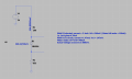
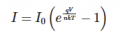
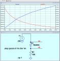
Unless I have completly misunderstood things, he seems to be using the change in current through the 100 Ohm sense resistor when the DUT is added to measure the voltage drop across the diode. However, as we all know, the V/I relationship for a diode is non linear so how can that possibly work?
1734645420812.png

To get this to work, it would need the diode equation to calculate the voltage!

1734683558932.png
 
Last edited:

ericgibbs

Joined Jan 29, 2010
21,487
hi,
The circuit shows current source values..
How is your +/-^v supply configured?
E

Update:
Could you post the full 1976 documentation for this project, so that we can see how the original designer intended the tester to be setup and used.?

EG57_ 2450.png
 
Last edited:

Thread Starter

brianmk

Joined Dec 23, 2016
102
hi,
The circuit shows current source values..
How is your +/-^v supply configured?
E

Update:
Could you post the full 1976 documentation for this project, so that we can see how the original designer intended the tester to be setup and used.?

View attachment 338506
"Could you post the full 1976 documentation for this project, so that we can see how the original designer intended the tester to be setup and used.?"
I already did that. See Post #7.

"How is your +/-^v supply configured?"
I use two separate 12V supplies. One has a switchable current limit (50mA / 300mA to allow for the extended collector current ranges) and feeds the main circuit.
The second 12V supply is floating (galvanically isolated) and is ony used to power the op amp. As per the original circuit, it uses two 820 Ohm resistors to create +/- 6V rails. The mid point of the two resistors connects to TR6 collector as in the original battery powered circuit. The only real difference is that the battery version gives +/- 4.5V rails for the op amp.

The actual circuit used doesn't feed the diode from a constant current source - it uses 820 + 33 ohm resistors. The more positive end connects to the fixed 12V supply, the other to Vc which is set to 10V. That gives 2V.

Perhaps the original circuit was never intended to provide accurate diode Vf measurements? It may be only intended to identify good/bad or silicon/germanium diodes? I get the impression that the diode capability and the If / Ices,Ir switch were probably only added as an after-thought.
BTW there are two serious errors in the schematic published in the original July edition. The corrections are given in the August edition. I made the corrections to the schematic before I attached it in Post #1.

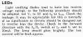
This section on testing LEDs may offer some additional information.
1734695065325.png

The description for LEDs above makes no sense either!
If the 'Ir/If' switch is set to If then the 'Ic' switch position (S3) is irrelevant.
Yet the description states that Ic should be set to 30mA ???

I am beginning to suspect that in an earlier version of the design, S2b did not exist.
That would allow S3 to be used to adjust the forward current.
Perhaps the circuit was changed but the operating instructions were never updated.

According to my calculations, assuming the LED forward voltage drop is 3V, Vc is set to 3V and the Ic current shunt is set for 1mA (100 Ohms), then the test current through the LED will be:-
(12V-3V)/(820+33+100) = 9mA which is close to the 8mA given above.
 
Last edited:

Thread Starter

brianmk

Joined Dec 23, 2016
102
Just as an aside, I found it interesting looking back at the 1976 PW magazines.
How technology and the ads have changed in the last 50years!

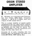
I found this ad for a 'P.E. Orion' 20W Stereo Amp.
I built this kit. I still have it and it still works and sounds good when driving a pair of 1970s Spendor BC1 Monitor speakers.

1734695311100.png

1734695762472.png
 

Thread Starter

brianmk

Joined Dec 23, 2016
102
When I tried using a germanium diode as the DUT, the error on the meter compared with a DMM is even worse.
This also happens in the simulation.

When I thought it through, I realised it's obvious that the voltage across the 100 Ohms sense resistor will be higher with a germanium diode compared to a silicon diode because there will be a lower voltage drop across the DUT.

It suddenly occurred to me that perhaps the meter scale needs to read in reverse!
First the DUT is shorted and Vc adjusted to give FSD.
When the short is removed, the voltage acoss the DUT is not approximated by the absolute meter reading but by the difference between the meter reading and full scale.

Using a modified LTSpice simulation with a 1N4004, the actual voltage across the DUT is 544mV.
With a 100uA FSD meter, the meter current is 42.8uA.
When read in reverse, this gives 100-42.8 = 57.2uA which corresponds to 572mV. A difference of 5%.

Using a germanium 1N34A the diode voltage is 280mV.
The meter current is 71uA which when read in reverse gives 100-71 = 29uA which corresponds to 290mV. A difference of 3.6%.

The simulation results agree closely with the results using the real hardware.

Does this make sense or have I lost the plot?
I have been struggling with this for so long I no longer trust my reasoning!
If I have got this right then why is it not mentioned in the original documentation?

If it is right then ideally the meter needs a separate scale in the reverse direction with 0 at the FSD position for use with If measurements.

I have also decided to get rid of S2b.
Instead, S3 can be set to the 1mA position for diode If measurements or the 10 or 30mA positions for LEDs.
 

Attachments

ericgibbs

Joined Jan 29, 2010
21,487
hi,
I worked on this project for a few hours yesterday, setting up the circuit is a pain, as you may have found the pots are interactive.
I understand the meter is 500uA and 3Vfsd.
The problems are caused by the way the 9V and the virtual ground voltage is set for project.EG57_ 2472.png

Look at this asc file.

E
 

Attachments

Thread Starter

brianmk

Joined Dec 23, 2016
102
hi,
I worked on this project for a few hours yesterday, setting up the circuit is a pain, as you may have found the pots are interactive.
I understand the meter is 500uA and 3Vfsd.
The problems are caused by the way the 9V and the virtual ground voltage is set for project.View attachment 338621

Look at this asc file.

E
Thanks for your efforts.

I am still baffled and scratching my head over this.
I have even been trying to discover if Ian Hickman is still alive and has a email address so I could ask him directly. As you probably know he is/was quite an expert who has written many electronics books over the years.

Comparing your simulations above with my own attempts, the main difference seems to be that you are assuming S1 (base current) is being used to set the forward current through the DUT. If that is the case then why does the description talk about shorting the DUT and adjusting V1 for FSD? I am not sure where R12 (18K) comes from: I assume you added that to adjust the current through the DUT to a required value rather than adjust V1? I also don't understand V3 (6.8V). Not that it makes any significant difference, but when R3=100, R4 + R6 should add to 999900.

Im my case, have been assuming S1 is left in position 'Ices' with S2a in position 'If' such that the forward current is determined by R13 + R14 (820+33) along with the 100 Ohm shunt R24+R25+R26+R27. When V1 is adjusted for FSD with the DUT shorted, the forward current is 2mA. The documentation section on testing LEDs seems to confirm that the Ib switch is left in the Ices position. However it also says the Ir/If switch should be in the If position and Ic set to 30mA. As I already pointed out, that makes no sense because in the If postion, the Ic switch (S3) has no effect. There seems to be a disconnect between the schematic and the operating instructions.

1734868046516.png
 

ericgibbs

Joined Jan 29, 2010
21,487
hi,
With my basic sim I was trying to find the correlation between the pots and the input signal.
I also use the original circuit

If I find anything helpful, I will post.
E
 
Top