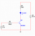
Transistor Switch

Thread Starter

IamConfused

Joined Oct 4, 2010
3
I have built this circuit and measured Ic, Ib and VCE for 0, 5, 10, and 15 Vbb input voltages. Now, I have to calculate the values of each.

For the base current:
Ib = (Vbb - Vbe)/Rb

I can't figure out how to calculate Ic
 

Attachments

R!f@@

Joined Apr 2, 2009
10,007
Ic≈ Ie-Ib.
Since Ib is negligable thus Ic≈Ie. (Ic is almost equal to Ie) Ie being in the μA range in most cases.

Ib will tend to increase in low gain transistors, sometimes in order of mA

Vbe will drop 0.6 to 0.7V typically for a silicone transistor when it is fully on

by the way, IMHO, IamConfused is not good nick to begin with. After a couple of posts u might still be regarded is still confused.
 
Last edited:

Jony130

Joined Feb 17, 2009
5,599
Your circuit will be in saturation if Ib is grater then Ib > [ (Vcc -V_led ) / β_min*Rc ] = (15V - 2V) / 50*1KΩ = 13V/50K = 260μA

And this will occurs for Vbb greater the
Vbb > 260μ * 10KΩ + Vbe = 2.6V + Vbe ≈ 3.2V
So If Vbb is grater then 3.2V BJT will be in saturation region.
And thats mean that Ic will be unchanged, and will be equal
Ic_max = ( Vcc - Vled - Vce(sat) ) / Rc ≈ 12.9mA
 

SgtWookie

Joined Jul 17, 2007
22,230
Well, in order for a 2N3904 transistor to be in saturation, from National Semiconductor's datasheet, Ib=Ic/10.
Min hFE is specified as 40, but that's when Ic=10mA and Vce=1.0, which is not in saturation; it is in the linear region.

In order to calculate the base resistor for most single transistors as saturated switches, you use β = 10.
So, to calculate Rbase, you'd use:
Rbase ~= (Vbb - Vbe) / (Ic/10)

Generally, you want Vce to be below 0.2v; this is operation in the saturated region. If the transistor comes out of saturation, power dissipation in the transistor will increase dramatically.

But, you first need to know the specifications of the LED for Vf @ current. A typical red LED might have a Vf of 2.1v @ 20mA current.

Then you need to calculate the value for your LED current limiting resistor R1.
R1 >= (Vsupply - (Vf_LED - Vce_sat)) / Desired_Current
For example:
R1 >= (15v - (2.1v - 0.1v)) / 20mA
R1 >= (15 - 2) / 0.02
R1 >= 13/.02
R1 >= 650 Ohms.
This is not a standard E24 value of resistance.
A table of standard values is here: http://www.logwell.com/tech/components/resistor_values.html
Bookmark that page.
Scanning down the green E24 columns, you'll see that 680 Ohms is the closest standard E24 value.

13v/680 Ohms = 19.1mA.

Now you have the values to calculate Rbase (R2)
Rbase <= (Vbb - Vbe) /(Ic/10)
Rbase <= (5v - 0.7v) / (19.1mA/10)
Rbase <= 4.3/.00191
Rbase <= 2251.3 Ohms
Looking back at the table of standard resistance values referenced earlier, you can see that 220 * 10 = 2,200 Ohms (2.2k) is the closest standard value of resistance <= 2251.3 Ohms.
 

Audioguru

Joined Dec 20, 2007
11,248
The minimum hFE of a 2N3904 when Vce is 1.0V and Ic is 10mA is 100, not 40.
The minimum hFE is 40 at a collector current of 0.1mA but its typical hFE (shown on a graph) is 230.
 

RRITESH KAKKAR

Joined Jun 29, 2010
2,829
Well, in order for a 2N3904 transistor to be in saturation, from National Semiconductor's datasheet, Ib=Ic/10.
Min hFE is specified as 40, but that's when Ic=10mA and Vce=1.0, which is not in saturation; it is in the linear region.

In order to calculate the base resistor for most single transistors as saturated switches, you use β = 10.
So, to calculate Rbase, you'd use:
Rbase ~= (Vbb - Vbe) / (Ic/10)

Generally, you want Vce to be below 0.2v; this is operation in the saturated region. If the transistor comes out of saturation, power dissipation in the transistor will increase dramatically.

But, you first need to know the specifications of the LED for Vf @ current. A typical red LED might have a Vf of 2.1v @ 20mA current.

Then you need to calculate the value for your LED current limiting resistor R1.
R1 >= (Vsupply - (Vf_LED - Vce_sat)) / Desired_Current
For example:
R1 >= (15v - (2.1v - 0.1v)) / 20mA
R1 >= (15 - 2) / 0.02
R1 >= 13/.02
R1 >= 650 Ohms.
This is not a standard E24 value of resistance.
A table of standard values is here: http://www.logwell.com/tech/components/resistor_values.html
Bookmark that page.
Scanning down the green E24 columns, you'll see that 680 Ohms is the closest standard E24 value.

13v/680 Ohms = 19.1mA.

Now you have the values to calculate Rbase (R2)
Rbase <= (Vbb - Vbe) /(Ic/10)
Rbase <= (5v - 0.7v) / (19.1mA/10)
Rbase <= 4.3/.00191
Rbase <= 2251.3 Ohms
Looking back at the table of standard resistance values referenced earlier, you can see that 220 * 10 = 2,200 Ohms (2.2k) is the closest standard value of resistance <= 2251.3 Ohms.

Hi,

It's sounds you have very good knowledge of biasing transistors for many applications, i have readied many books but don't get any good details of it, please tell any link for learning biasing of BJT.

Thanks.
 
Top