Facebook
 Google
 GitHub
 Linkedin

Basically I am reading a transistor switch example fron Horowitz Hill book - The art of electronics.
He starts by explaining that there are 4 golden rules for transistors:
1) Collector must be more positive than the emitter
2)base-emitter and base-collector act like diodes
3)transistors have max values for Ic, IB and VCE that cannot be exceede
4) when rules 1-3 are applied Ic is approximately IB that is (Ic=βIb)
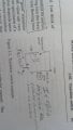
Going deeper into the example he explains when the switch is closed that.
1) base rises to .6V
2) voltage drop across base resistor is 9.4V
3) base current is 9.4mA
4) application of rule 4 leads to Ic = 940ma (for a typical β=100) which is wrong, wrong, wrong! Because rule 4 only holds when rule 1 is obeyed
So here is where things get confusing for me.
If Ic is 940ma how are you breaking the rule that collector voltage is not greater than emitter voltage?
He says to have a current of 940mA can only occur if you would pull the collector below ground. I totally dont understand this statement!
What exactly does this mean?
How would you pull a collector below ground?
Please help!
He starts by explaining that there are 4 golden rules for transistors:
1) Collector must be more positive than the emitter
2)base-emitter and base-collector act like diodes
3)transistors have max values for Ic, IB and VCE that cannot be exceede
4) when rules 1-3 are applied Ic is approximately IB that is (Ic=βIb)
Going deeper into the example he explains when the switch is closed that.
1) base rises to .6V
2) voltage drop across base resistor is 9.4V
3) base current is 9.4mA
4) application of rule 4 leads to Ic = 940ma (for a typical β=100) which is wrong, wrong, wrong! Because rule 4 only holds when rule 1 is obeyed
So here is where things get confusing for me.
If Ic is 940ma how are you breaking the rule that collector voltage is not greater than emitter voltage?
He says to have a current of 940mA can only occur if you would pull the collector below ground. I totally dont understand this statement!
What exactly does this mean?
How would you pull a collector below ground?
Please help!
Attachments
-
 287.6 KB Views: 52