Transistor Substitute

Thread Starter

AndyL5

Joined Jan 4, 2025
19
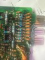
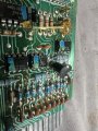
Oops sorry I must be going partly color blind. It is green brown red so 5100 ohms. I initially thought I saw green black red. Is that a significant difference? I can measure +5v coming off of the IC to this resistor. Can see the resistor in this photo under the glue thread.
 

Attachments

sghioto

Joined Dec 31, 2017
8,634
Not a significant difference.
Can you get a voltage reading on the collector of one of the good transistors with the relay activated?
 

Thread Starter

AndyL5

Joined Jan 4, 2025
19
OK with the circuit connected to the 73ohm Bosch relay and switched on, I get 5V from the IC to the 5.1K resistor, 1.38V on the base, 0V on the emitter and 0.731V on the collector (which is the leg tracked off to the relay)
 

Ian0

Joined Aug 7, 2020
13,132
OK with the circuit connected to the 73ohm Bosch relay and switched on, I get 5V from the IC to the 5.1K resistor, 1.38V on the base, 0V on the emitter and 0.731V on the collector (which is the leg tracked off to the relay)
That's a darlington.
Use the MPSA14.
 

Thread Starter

AndyL5

Joined Jan 4, 2025
19
Ah thankyou. I was just trying to find the MPSA14 and it was coming up not available. I cannot buy them locally here in NZ but can get from Element14.
Appreciate your advice.
 

Ian0

Joined Aug 7, 2020
13,132
MPSA14 is obsolete.
The MPSA29 is available with a higher current rating.
Bc517 is another alternative, or KSP13 which is a Samsung‘s version of the MPSA13 when their semiconductor division was bought by OnSemi.
ONSemi still has the MPSA14 datasheet on their website.
 

Thread Starter

AndyL5

Joined Jan 4, 2025
19
Yes RS have them. I will buy from RS because they have a slightly cheaper delivery service.
Appreciate the help from you folks.
Will report back on the repair.
 

Thread Starter

AndyL5

Joined Jan 4, 2025
19
I received the BC517's today. Excuse my ignorance, but could someone please fact check me here on the physical installation. You can see the upper two old transistors in the attached photo, which have the right leg tracked off to the relay output circuit. I am assuming that the RH leg on these old 3248 devices is the Collector - correct.? The data sheet for the BC517 shows the emitter would be that leg if I were to physically install the new device in the same orientation.... Assuming that the BC517 needs to be installed opposite orientation.?
 

Attachments

sghioto

Joined Dec 31, 2017
8,634
Assuming that the BC517 needs to be installed opposite orientation.?
That would be my assumption but it should be easy to figure out what the pins on the old transistor connect to.
Emitter to ground.
Base to one end of the 5.1K resistor
Collector to the relay coil.
1736994363832.png
 
Top