transistor necessity

Thread Starter

mxabeles

Joined Apr 25, 2009
295
hey there,
when I have a circuit running that lights up various leds without using a tranistor the logic acts funny. Using transistors to drive the leds makes the funky errors disappear. Am I correct in thinking that this is because the base of transistor takes so little current that it doesn't "interrupt" or "confuse" the signal flow, which seemingly does happen if devices are powered by logic unaided by transistors?
Thanks,
M
 

hgmjr

Joined Jan 28, 2005
9,027
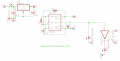
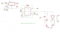
To assess the difference in performance of the two circuits (one with and one without transistors) it would help us if you would please post the two schematics?

hgmjr
 

Thread Starter

mxabeles

Joined Apr 25, 2009
295
and as an aside great website i was looking at but got off put by this:
'the collector is a current source: it does not source a voltage'
this is concerning npn transistor. Now i must say i am still not solid about voltage/current relationship (even after reading, there is no such thing as electrons haha). In my mind i thought current and voltage are forever linked, how can you have one without the other...ever?
thanks 2,
M
 

beenthere

Joined Apr 20, 2004
15,819
In my mind i thought current and voltage are forever linked, how can you have one without the other...ever?
While you can't have current without a potential difference to move electrons (voltage), you can have a voltage and no current. Open a switch, and you can read a voltage across the contacts, but there will be no current.
 

Thread Starter

mxabeles

Joined Apr 25, 2009
295
been there : thanks, thats interesting. Does that make the case that its not high voltage that burns out say an led but current? That, among other things, is still a sticking point. In other words, using series resistors although they drop voltage as a bi-product of limiting current, are truthfully used to limit current to device not voltage.
thanks again,
m
 

hgmjr

Joined Jan 28, 2005
9,027
Your assessment of the advantage provided by the addition of a transistor is pretty accurate. One thing, from looking at your circuit that includes the transistor, you need to add a current limiting resistor between the output of the 555 and the base of the transistor. Otherwise you are clamping the output of the 555 timer at around 0.7 volts.

hgmjr
 

Thread Starter

mxabeles

Joined Apr 25, 2009
295
right, actually tho i'm using 2803 array they got built in series resistor. The reason its not in the schematic is that eagle doesn't seem to have the uln2803a in its library. U know of any downloads of it...might have to learn how to make my own libraries after all :))
 

beenthere

Joined Apr 20, 2004
15,819
its not high voltage that burns out say an led but current?
The PN junction has to have a certain voltage across it before electrons overcome the barrier, but after that, there is no "natural" limiting mechanism present to control current. As power is E X I, that power dissipated in the PN junction will heat the LED to destruction.
 

Audioguru

Joined Dec 20, 2007
11,248
Why do people post "wrong" schematics just because the real part model is not in the library?

Use an accurate drawing program to draw an accurate schematic not a pcb designing program that does it wrong.
 

SgtWookie

Joined Jul 17, 2007
22,230
right, actually tho i'm using 2803 array they got built in series resistor. The reason its not in the schematic is that eagle doesn't seem to have the uln2803a in its library. U know of any downloads of it...might have to learn how to make my own libraries after all :))
They are in the uln-udn.lbr - if you don't have it, you can download it from the CadsoftUSA site, or if it is not there any longer, I could upload the one I have for you.
 
Top