Transistor in Active and saturation region

Jony130

Joined Feb 17, 2009
5,488
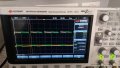
You have incorrectly interpreted the result of your measurements.
Your BJT's is saturated the Vce voltage is around 1.9V when the BJT is OFF.

Taka a look at the simulation results:

1.PNG

For this circuit

d.PNG


As you can see the Vce is not equal to 3.3V when the BJT's is OFF because the scope probe is loading the circuit and there will be some voltage drop across the LED.
 

crutschow

Joined Mar 14, 2008
34,432
Do the test with the resistor but without the LED to see the output goes from near 0V (saturated) to the supply voltage (off).
 

WBahn

Joined Mar 31, 2012
30,058
waiting someone to respond ???

Thanks
So if someone doesn't respond in less than 75 minutes you feel ignored?

People here have lives -- jobs, families, sleep, etc. -- and are not sitting here monitoring their computers just so that they can respond to your request for free assistance from strangers in the time frame you feel you are owed it.

Please try to keep that in mind -- members respond to those posts that attract their attention on their own schedule. It may take several hours before someone even sees your post.
 

WBahn

Joined Mar 31, 2012
30,058
Further to discussion ..please find attched schematic and Vce waveform...

Why transistor not in saturation....vce is around 1.85 V
What you are measuring is the difference between Vce when the transistor is on and when it is off. What you need to measure is the voltage of the bottom of the square wave relative to the circuit common to get Vce when the transistor is on. Increase the channel gain so that you can get a good measurement -- fill up as much of the screen vertically as you can.

You can see that this is going to be a very small value, indicating that the transistor is in hard saturation, which is what you would expect. I can't tell for sure because you haven't indicated what your test set up is like (how you are using the probe to make the measurement). If Vce is, say, 0.3 V and if the LED is dropping the nominal 1.8 V then you have about 1.2 V across the 100 Ω resistor yielding about 12 mA. Note that measuring the voltage across the collector resistor directly would give you a much better indication of the current that is flowing.

If the Vbe is about 0.7 V, then you have about 70 μA going through the resistor across the BE junction and about 260 μA flowing in the other resistor, leaving about 190 μA flowing in the base. To get 12 mA of current this needs a beta of about 63. That's too much to be in the usual classification range for saturation, but it may well be enough to put the Vce into the usual saturation voltage range for that transistor.
 

Thread Starter

mishra87

Joined Jan 17, 2016
1,036
Thank you so much you all for your reply and time.

I am a bit confused that some one says the above circuit is working in saturation and some says it does not saturate ....

Although I have measured in scope and found transistor working in saturation.

I have removed LED and tested found attched waveform.

Now I have few queries left with me...

1. When led is not connected current through 100E is 13.2 mA.

2. When I connect led with 100E current reduces to 5.2 mA ...why this is happening (meaured with DMM).

3. Is there any risk transistor does go in saturation ???

4. Why there is delay between input and output ...yellow is base signal in waveform and green is voltage across Vce.

Regards,
Shiv
 

Attachments

Jony130

Joined Feb 17, 2009
5,488
1. When led is not connected current through 100E is 13.2 mA.
Did you measure it with a DMM set at DC current?
If so, the ammeter will show the average current equal to about Idc = Ic_peak*D ≈ 3.3V/100Ω * 0.5 ≈ 16mA
Where:
Ic_peak = (Vsup - Vce(sat))/(RC + R_DMM)
D - square wave duty cycle D = Ton/(Ton + Toff) = Ton/T

R_DMM ≈ 10Ω for a cheap DMM at mA range.

2. When I connect led with 100E current reduces to 5.2 mA ...why this is happening (meaured with DMM).
The same situation as before

Ic_peak = (Vsup - Vce(sat) - VF)/(Rc + R_DMM) ≈ (3.3V - 2V)/100Ω ≈ 13mA Therefore I_DC = Ic_peak *D ≈ 13mA*0.5 ≈ 6.5mA

3. Is there any risk transistor does go in saturation ???
What risk?

4. Why there is delay between input and output ...yellow is base signal in waveform and green is voltage across Vce.
Well, this delay is caused by the BJT's internal parasitic capacitances. And we call this delay a Storage time.
Storage time
(ts) is the time required for the BJT to come out of saturation.

New1.PNG

In this case the Storage time is around ts ≈ 1.5μs

And we can reduce the storage time by adding an anti-saturation diode (Baker clamp) and the Shockley diode is the best for this job.

New2.PNG

The Storage time is reduced to ts ≈ 0.3μs

But the speed-up capacitor will also do the job.

new3.PNG
 
Last edited:

WBahn

Joined Mar 31, 2012
30,058
Thank you so much you all for your reply and time.

I am a bit confused that some one says the above circuit is working in saturation and some says it does not saturate ....
Several possible reasons, among them (1) some people may not have interpreted your data correctly, and (2) the notion of "saturation" is not some hard and fast rule -- a transistor operates across a continuum in which above some level everyone pretty much agrees that it is in the linear region and below some different level everyone pretty much agrees that it is in saturation. But between those points some people will call it saturated and some won't.

Although I have measured in scope and found transistor working in saturation.

I have removed LED and tested found attched waveform.

Now I have few queries left with me...

1. When led is not connected current through 100E is 13.2 mA.
How are you making the measurement? Putting a DMM configured for current in series with the resistor, or measuring the voltage across the resistor (which is generally the better method)? Are you running the circuit in a static condition while you make the measurement, or is the input signal your square wave? It makes a HUGE difference. I'm going to assume you are running it in a static condition with a high input voltage.

That would mean that the voltage across it is 1.32 V, leaving a Vce of 1.98 V which would mean that the transistor is not even close to saturation.

It would really help if you gave us all the data for the circuit -- particularly the voltages at each of the nodes.

2. When I connect led with 100E current reduces to 5.2 mA ...why this is happening (meaured with DMM).
Because the LED drops some of the voltage, leaving less voltage to be dropped across the current-limiting resistor. The difference of 8 mA means that the voltage across the 100 Ω resistor dropped by

Here is where it would really help to have some additional information, particularly either the voltage across the LED or the Vce voltage of the transistor.

About all we can say here is that the voltage across the 100 Ω resistor is 0.52 V. Beyond that, we have to GUESS that the voltage across the LED is something in the vicinity of 1.8 V, making the Vce of the transistor something in the 2.3 V range.

More information would sure be nice.

3. Is there any risk transistor does go in saturation ???
It's hard to understand the context of that question without more information about what you are trying to do? This sounds like you want to keep the transistor from going into saturation. Why? There are modifications you can make to the circuit to prevent it from going into saturation (or at least hard saturation).

What is it that you are trying to achieve?

4. Why there is delay between input and output ...yellow is base signal in waveform and green is voltage across Vce.
There's an effective capacitance resulting from charge storage in the base junctions that has to be transferred before it can come out of saturation. With a large series base resistor, that takes time.
 

Thread Starter

mishra87

Joined Jan 17, 2016
1,036
Did you measure it with a DMM set at DC current?
If so, the ammeter will show the average current equal to about Idc = Ic_peak*D ≈ 3.3V/100Ω * 0.5 ≈ 16mA
Where:
Ic_peak = (Vsup - Vce(sat))/(RC + R_DMM)
D - square wave duty cycle D = Ton/(Ton + Toff) = Ton/T

R_DMM ≈ 10Ω for a cheap DMM at mA range.


The same situation as before

Ic_peak = (Vsup - Vce(sat) - VF)/(Rc + R_DMM) ≈ (3.3V - 2V)/100Ω ≈ 13mA Therefore I_DC = Ic_peak *D ≈ 13mA*0.5 ≈ 6.5mA


What risk?


Well, this delay is caused by the BJT's internal parasitic capacitances. And we call this delay a Storage time.
Storage time
(ts) is the time required for the BJT to come out of saturation.

View attachment 175907

In this case the Storage time is around ts ≈ 1.5μs

And we can reduce the storage time by adding an anti-saturation diode (Baker clamp) and the Shockley diode is the best for this job.

View attachment 175908

The Storage time is reduced to ts ≈ 0.3μs

But the speed-up capacitor will also do the job.

View attachment 175909

Thank you so much you time and these valuable information Mr. WBahn.

This information probably help a Google user .

The unsaid left what is risk .
So my question was in above circuit design I want to operate transitor in sauration mode and drive led ...so considering Rc = 100E and Rb=10K/10K ...is there any posibility that transistor not to operate in saturation region.

Thanks again:
Regards,
Mishra
 

Thread Starter

mishra87

Joined Jan 17, 2016
1,036
Several possible reasons, among them (1) some people may not have interpreted your data correctly, and (2) the notion of "saturation" is not some hard and fast rule -- a transistor operates across a continuum in which above some level everyone pretty much agrees that it is in the linear region and below some different level everyone pretty much agrees that it is in saturation. But between those points some people will call it saturated and some won't.


How are you making the measurement? Putting a DMM configured for current in series with the resistor, or measuring the voltage across the resistor (which is generally the better method)? Are you running the circuit in a static condition while you make the measurement, or is the input signal your square wave? It makes a HUGE difference. I'm going to assume you are running it in a static condition with a high input voltage.

That would mean that the voltage across it is 1.32 V, leaving a Vce of 1.98 V which would mean that the transistor is not even close to saturation.

It would really help if you gave us all the data for the circuit -- particularly the voltages at each of the nodes.


Because the LED drops some of the voltage, leaving less voltage to be dropped across the current-limiting resistor. The difference of 8 mA means that the voltage across the 100 Ω resistor dropped by

Here is where it would really help to have some additional information, particularly either the voltage across the LED or the Vce voltage of the transistor.

About all we can say here is that the voltage across the 100 Ω resistor is 0.52 V. Beyond that, we have to GUESS that the voltage across the LED is something in the vicinity of 1.8 V, making the Vce of the transistor something in the 2.3 V range.

More information would sure be nice.


It's hard to understand the context of that question without more information about what you are trying to do? This sounds like you want to keep the transistor from going into saturation. Why? There are modifications you can make to the circuit to prevent it from going into saturation (or at least hard saturation).

What is it that you are trying to achieve?


There's an effective capacitance resulting from charge storage in the base junctions that has to be transferred before it can come out of saturation. With a large series base resistor, that takes time.
Thank you so much..

Yes I measured current by putting DMM in series with resistor 100E.

VF_Led = 1.2V meaured by DMM
Vce (sat) = 300mG

I want to operate transitor in saturation region and drive the LED.

So Rc= 100 E. ..will it always work in saturation mode with base Rb= 10k/10k.

Thanks .
 

crutschow

Joined Mar 14, 2008
34,432
.will it always work in saturation mode with base Rb= 10k/10k.
What do you mean 10k/10k? There is only one base resistor.
The base resistor value is correct for only a specific maximum collector current.
To insure saturation, the base current should be 5-10% of the collector current.
 

Jony130

Joined Feb 17, 2009
5,488
What do you mean 10k/10k? There is only one base resistor.
The base resistor value is correct for only a specific maximum collector current.
To insure saturation, the base current should be 5-10% of the collector current.
From what I understand "between the pages" because TS does not explain it well. The TS is using this BJT MUN5211
https://www.onsemi.com/PowerSolutions/product.do?id=MUN5211DW1
And as you can see this BJT's already have a built-in the base current limiting resistor and pull-down resistors 10k/10k.

Also modern LED does not need such a high forward current (15mA) the 5mA or less should be enough to do the job.
 

Thread Starter

mishra87

Joined Jan 17, 2016
1,036
What do you mean 10k/10k? There is only one base resistor.
The base resistor value is correct for only a specific maximum collector current.
To insure saturation, the base current should be 5-10% of the collector current.
Hi Mr. crutschow !!!

Thanks ,
MUN5211 is having 10 current limiting and 10k pull down resistor ...

And you mean to say (3.3-0.7)/10k = 260uA.

0.7/10k =70 uA. .

So current going in base is only 190uA ...

So Ic= 190uA*80 (beta) = 15.2 mA

Beta = 80 in graph given in datasheet

And that 190uA base current is not enough to drive transistor into saturation...isn't it ...

Thanks ???
 

WBahn

Joined Mar 31, 2012
30,058
Thank you so much..

Yes I measured current by putting DMM in series with resistor 100E.

VF_Led = 1.2V meaured by DMM
Vce (sat) = 300mG

I want to operate transitor in saturation region and drive the LED.

So Rc= 100 E. ..will it always work in saturation mode with base Rb= 10k/10k.

Thanks .
Which is the true objective -- the drive the LED so that it is clearly on, or to operate the transistor in saturation?

Think of it this way -- I offer you two circuits -- one puts the transistor firmly into saturation but the LED is very dim while the other lights up the LED quite clearly but the transistors isn't in saturation. Will either of those two circuits be acceptable to you, or is neither acceptable?
 

WBahn

Joined Mar 31, 2012
30,058
Hi Mr. crutschow !!!

Thanks ,
MUN5211 is having 10 current limiting and 10k pull down resistor ...

And you mean to say (3.3-0.7)/10k = 260uA.

0.7/10k =70 uA. .

So current going in base is only 190uA ...

So Ic= 190uA*80 (beta) = 15.2 mA

Beta = 80 in graph given in datasheet

And that 190uA base current is not enough to drive transistor into saturation...isn't it ...

Thanks ???
You can't mix the high value of beta when the transistor is NOT in saturation with the low value of beta that is the hallmark indicator that the transistor IS in saturation. As you move to saturation the beta of the transistor falls. Most manufacturers operate small signal transistors at a beta of 10 when measuring their device parameters in saturation.
 

Thread Starter

mishra87

Joined Jan 17, 2016
1,036
Thank you sou much for all your information.

I decided to go with base resistance 4.7K to make sure transistor always operate in saturation region.

Regards,
mishra
 

sparky 1

Joined Nov 3, 2018
757
The mathematical process differs from solving as a quantitative method step by step compared to a mechanical process.
The manufacturer may have a batch of transistors that are close under ideal conditions as you approach saturation with a given electrical input.
Familiarity or review with general understanding of terms is straightforward.


Sometimes we make notation on the print out of a data sheet along with your specific schematic and your specific parts.
It may already work for your test board but sometimes the results are less than perfect. Having a good feel for approximation or feel comes from watching what happens when you approach your circuit with a warm soldering iron for example. The notation is put in a suitable folder complete documentation really helps to be organized so your own process be made available later even if it is a simply a basic transistor
circuit it sounds like you are developing skills or acquiring what it takes.
 
Last edited:

Thread Starter

mishra87

Joined Jan 17, 2016
1,036
The mathematical process differs from solving as a quantitative method step by step compared to a mechanical process.
The manufacturer may have a batch of transistors that are close under ideal conditions as you approach saturation with a given electrical input.
Familiarity or review with general understanding of terms is straightforward.


Sometimes we make notation on the print out of a data sheet along with your specific schematic and your specific parts.
It may already work for your test board but sometimes the results are less than perfect. Having a good feel for approximation or feel comes from watching what happens when you approach your circuit with a warm soldering iron for example. The notation is put in a suitable folder complete documentation really helps to be organized so your own process be made available later even if it is a simply a basic transistor
circuit it sounds like you are developing skills or acquiring what it takes.
Sounds good !!
Interesting to know new term i.e. force beta.
What is force beta in lecture.
How do we calculate force beta value.

Beta_Force = ic/ib
and then where to get ic value :
Could you explain some calculation for better understanding .
 
Last edited:
Top