Transistor driven by one voltage that switches another voltage?

Thread Starter

electronice123

Joined Oct 10, 2008
339
Hi all,

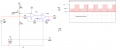
I'm trying to build a circuit which will give me a series of pulses across the load at one voltage then at a lower voltage.

I designed the circuit in multisim and it worked great the first time....But in real life its not working right.

When I remove Vee in multisim and ground that point to the other circuit ground I get exactly what I need.....But in real life when I do that the amplitude across the load drops to nothing.


Can anyone tell me what I'm doing wrong?

I am using a dual power supply and dual channel signal generator.
 

wayneh

Joined Sep 9, 2010
17,496
In the real world, is there actually a current path from -5V Vee to the same ground as used by the rest of the circuit? The voltage at the base of Q4 would keep it fully on all the time, since it would be varying between +5V and +17V relative to the emitter voltage.

You may also need a resistor to limit the base current on Q1.
 

Thread Starter

electronice123

Joined Oct 10, 2008
339
Initially I had the 12V ground on the ic's seperate from the signal generators ground...I now have them connected together. However, the ground at q4 is isolated from the rest of the circuit....

I tried different values of resistance at the Q1 base but still didn't get it to work.
 

Thread Starter

electronice123

Joined Oct 10, 2008
339
When I ground Vee to the rest of the circuit the voltage across the load drops to the pV range?

Somewhere I'm doing something wrong...All the signals look great until I look across the load?
 

DGElder

Joined Apr 3, 2016
351
Not sure I understand exactly what the problem is or what you are doing but.... If you change the point connected to Vee to ground instead you reduce the drive voltage at the output by half, even worse when you account for all the Vce voltage drops in the output; so of course the output is going to be highly reduced. Have you tried grounding the output at the bottom of the 10 ohm resistor?
 
Last edited:

Thread Starter

electronice123

Joined Oct 10, 2008
339
Haven't tried that...I will today though.

As you can see I have two frequency generators. The higher frequency is meant to be the frequency that drives the load, the low frequency modulates the voltage. The potentiometer adjusts the offset.
 

AnalogKid

Joined Aug 1, 2013
10,986
You opened a thread in the Projects forum with a different title but the same question. Please pick one and ask the moderator to close the other.

ak
 

Thread Starter

electronice123

Joined Oct 10, 2008
339
You opened a thread in the Projects forum with a different title but the same question. Please pick one and ask the moderator to close the other.

ak
Sorry about that....I didn't get any replies on the projects forum so I posted over here. I tried to delete the post before any replies were given but could not see an option to do it.

I have a new schematic that will hopefully make it easier to see what I'm trying to do. My last circuit was way off how I had the transistors connected so I understand the confusion and I apologize as that was my mistake.

So, V1 and V2 both produce a 50% duty cycle square wave frequency of 10V with a 5V offset so neither pulse goes below 0V.
I am trying to pulse the load at V1's frequency then modulate the voltage using V2's frequency....So the load will be continually pulsed but the voltage will change determined by the pulsing of V2.

My question is, how do I connect the transistors so that they will do this?
 

Attachments

Alec_t

Joined Sep 17, 2013
14,280
Yes (a left-over from a previous draft). My bad. Feedback to the inverting input should not be direct from the opamp output pin.
 

AnalogKid

Joined Aug 1, 2013
10,986
You're putting a 12 V p-p waveform into an inverting amplifier powered by only +12 V. Even if the input common mode range included both power rails, the only DC offset that would produce a clean output is 12 V. Any adjustment of the offset pot and the opamp output will saturate against one rail.

Neither of the waveform drawings have voltage levels or a ground reference, so it is not clear at all what is going on.

Also, the "what I need" waveform looks like it never goes below GND, yet you have a TIP120 pulling the load to -5 V. ??? What is the relationship with both 10 ohm resistor terminals and GND? Or, what are the voltages (with respect to GND) for the bottom, lower peak, and higher peak output voltages?

A TIP120 is rated for 5 A and your max output current is 1 A, so there is no need for the 2N3055.

R1 is way too small, allowing almost 60 mA of base current where 2 mA is sufficient. Consider 1.0 K - 2.2 K.

ak
 

Alec_t

Joined Sep 17, 2013
14,280
But I need to have the offset adjustable?
Offset from what? Your wanted waveform seems to show positive voltages only (ground referenced?), so a simple voltage divider (potentiometer) supplied with your maximum required Vx volts can give you any lower voltage Vy that you want.
Tell us what the required voltages are at the waveform's least positive point, most positive point and the intermediate point.
 

Alec_t

Joined Sep 17, 2013
14,280
What is "it"? Do you mean the waveform's least positive point, most positive point or the intermediate point? There are three voltages involved: what are they?
 

AnalogKid

Joined Aug 1, 2013
10,986
I need it to be adjustable from 2V to the supply voltage of 10V.
It - ?!?!?!?!? Eighteen posts back and forth, and your requirements STILL are not clear.

How about this - take a moment. Think about how you would explain your circuit to a total stranger, someone who does not know any of the secret requirements. Think about how to label or identify each node in the circuit. Think about unique names for each signal and each circuit function. Think about using precise, unambiguous language to communicate with a professional who knows more than you, but knows nothing about you. Think about why you are holding back details, such as where you are located.

Think, then write. It saves time, every time.

ak
 
Last edited:

Thread Starter

electronice123

Joined Oct 10, 2008
339
new dwg.png I have two signal generators that produce an adjustable frequency square wave ( each at a 50% duty cycle) of positive polarity (neither square wave goes below 0V).
The signal generator V1 produces a higher frequency than V2
The circuit is meant to produce positive square waves (with reference to gnd) across the load at a high voltage amplitude then produce positive square waves across the load at a lower voltage amplitude, the time period of each voltage level is determined by V2 's frequency and duty cycle.

The signal generators use +10V as well as the Op Amp(s). The power source V3 driving the load is adjustable from 0 to +10V.

The circuit worked in multisim but not on the breadboard..

So you can see what I am trying to do-The scope shot hopefully explains it best.[
 
Last edited:
Top