Transistor as invertor switch

Thread Starter

abuhafss

Joined Aug 17, 2010
318
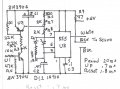
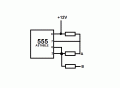
In a 555 astable circuit, I would like to use a transistor as an inverter switch between points A and B such that when the base is high, A and B remain open and when the base is low, A and B get closed. Can somebody help me how to do it.

Thanks for the help.
 

Attachments

aws505

Joined Mar 11, 2013
59
So you would like to have a transistor that acts to short the points A and B in your schematic? How is the base of this transistor driven? By another 555 perhaps? Also, your logic for the base of the transistor is backwards, when the base of the transistor is held high, it will short A to B and when the base of the transistor is low, there will be an open-circuit from A to B.

Can you clarify your question a bit, please?
 

Thread Starter

abuhafss

Joined Aug 17, 2010
318
So you would like to have a transistor that acts to short the points A and B in your schematic? How is the base of this transistor driven? By another 555 perhaps? Also, your logic for the base of the transistor is backwards, when the base of the transistor is held high, it will short A to B and when the base of the transistor is low, there will be an open-circuit from A to B.

Can you clarify your question a bit, please?
Yes the logic is backwards.
When there is signal at the base, A-B open circuit.
When no signal at the base, A-B short
 

Bernard

Joined Aug 7, 2008
5,784
I would use a 4066, analog-digital switch if the R values are in 10k range, or maybe a transistor photo coupler, collector to highest +V.
 

aws505

Joined Mar 11, 2013
59
You can always go the lazy route and make an inverter on the gate of the transistor. It only requires an additional transistor and a resistor. Very cheap'o way to implement this behavior.
 

Thread Starter

abuhafss

Joined Aug 17, 2010
318
You can always go the lazy route and make an inverter on the gate of the transistor. It only requires an additional transistor and a resistor. Very cheap'o way to implement this behavior.
Thanks for your advice, I have been considering to use RTL inverter but I am confused how to manage the connections between point A and B. Could you please show me your example on my provided picture?
 

Bernard

Joined Aug 7, 2008
5,784
I believe that you will have trouble using a transistor as a switch as there is no solid reference for the base. I am using something similar, basic period is 20 msec, a short + pulse,.7 ms, or long, 1.8 ms to drive a servo. If input is LO , pulse is long, if input is HI, U1 & U2 conduct, shorting R6 & R7, giving shorter pulse. Leaving out U1, using X as input ,operation is reversed, but X must go to top rail-U3-8.
Can you explain the timing that you wish to achieve?
 

Attachments

tubeguy

Joined Nov 3, 2012
1,157
It might be good to let us know what your final goal is with circuit. Could you post a more complete schematic?
 
Top