Facebook
 Google
 GitHub
 Linkedin
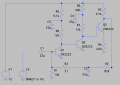
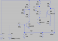
made this but having little problem.. The voltages check out except the voltage at the collector of Q3 which TS wants it to be 5v but getting about 0.9v
Like, it's working on spice but not real
Please what's problem?
In real, there's a 22uf across Vcc
Also, any one that uses the spice : see what happens if the input signal is connected and 2.6nf (tried others on spice) is connected at base of Q3
Thanks thanks
Like, it's working on spice but not real
Please what's problem?
In real, there's a 22uf across Vcc
Also, any one that uses the spice : see what happens if the input signal is connected and 2.6nf (tried others on spice) is connected at base of Q3
Thanks thanks
Attachments
-
 212.1 KB Views: 24
 -
4.9 KB Views: 6