
 Facebook
 Google
 GitHub
 Linkedin
Hi there
I am currently doing an introductory course that looks at electronics and have been assigned the task of designing three transistor amplifiers. These are a Common Emitter, a Common Collector and a Common Base amplifiers.
Now I am currently using National Instrumentations multisim to perform simple simulations to look at the responce of an analoge input voltage. During the course of these simulations certain problems have occured that I cant get my head around.
Now I am not great at maths and have used a simple method in which to design the common emitter circuit.
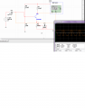
The problem that I have been having is that when I introduce the capacitor across the emitter resistor I effectivley create a sqaure wave a picture for which can be found below now.
Secondly, I have designed a common collector amplifier again using my basic maths. In the case of this it seem that the voltage output I get matches what theory suggest that the voltage drop will be ~0.6-0.7volts. When I look at the current gain however it seems as though there is actully a reduction in current rather than an increase relative to β. Again a picture has been attached below.
Any ideas?
Finaly would anyone have a resource that prevides a guide on how to simply design a Common Base transistor the ones that i have found use maths that I am unfamilier with.
If anyone would be able to recommend a book that explains the above in laymans terms that would be great.
Many thanks
Ishtar
I am currently doing an introductory course that looks at electronics and have been assigned the task of designing three transistor amplifiers. These are a Common Emitter, a Common Collector and a Common Base amplifiers.
Now I am currently using National Instrumentations multisim to perform simple simulations to look at the responce of an analoge input voltage. During the course of these simulations certain problems have occured that I cant get my head around.
Now I am not great at maths and have used a simple method in which to design the common emitter circuit.
The problem that I have been having is that when I introduce the capacitor across the emitter resistor I effectivley create a sqaure wave a picture for which can be found below now.
Secondly, I have designed a common collector amplifier again using my basic maths. In the case of this it seem that the voltage output I get matches what theory suggest that the voltage drop will be ~0.6-0.7volts. When I look at the current gain however it seems as though there is actully a reduction in current rather than an increase relative to β. Again a picture has been attached below.
Any ideas?
Finaly would anyone have a resource that prevides a guide on how to simply design a Common Base transistor the ones that i have found use maths that I am unfamilier with.
If anyone would be able to recommend a book that explains the above in laymans terms that would be great.
Many thanks
Ishtar
Attachments
-
 75.4 KB Views: 28
 -
 59.4 KB Views: 27






