Transimpedence amplifier

Thread Starter

Saravana Vilashini M

Joined Apr 16, 2020
44
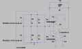
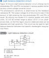
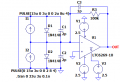
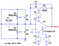
I am building a circuit which has OPAMP and inputs to the OPAMP from the photodiode. I have replaced the photodiode with the equivalent circuit. Aim is to cancel the noise. Output should be the subtraction of two input currents. Attached the LTSpice file.
 

Attachments

OBW0549

Joined Mar 2, 2015
3,566
Although many here use LTSpice, not all do. You may get more help if you also include a screen grab of your schematic, preferably in .png format.
 

danadak

Joined Mar 10, 2018
4,057
Your TIA conversion G is quite low, re the 1k ohm fdbk R. And your 100M ohm
input Rs generating a lot of thermal noise, Mostly uncorrelated, so subtraction
not effective.

I am not an expert here, what am I missing.


Regards, Dana.
 

Analog Ground

Joined Apr 24, 2019
460
The signals from the two photodiodes caused by light will subtract because they are opposite in polarity. However, the intrinsic noise from the two photodiodes will add as the RMS of two noise sources. This is because the two noise sources are uncorrelated. The LTSpice noise simulations will show this additive effect. This AAC article can get you started on simple noise simulations if you don't know how to do it in LTSpice.

https://www.allaboutcircuits.com/technical-articles/Noise-Analysis-Using-LTspice-Tutorial/
 

Danko

Joined Nov 22, 2017
2,165
I have replaced the photodiode with the equivalent circuit
What is p-n transition area of your photodiode?
If it is 67 square centimeters and under sunlight,
then current will about 2A, like in your simulation.
Seems current in range 10~20uA will be more realistic.
 
Last edited:

Thread Starter

Saravana Vilashini M

Joined Apr 16, 2020
44
Thanks for the link.
- The signals from the two photodiodes caused by light will subtract because they are opposite in polarity.
At the output of the photodiodes, signals are not getting subtracted. Please suggest me if i have done any mistake.
 

Danko

Joined Nov 22, 2017
2,165
- The signals from the two photodiodes caused by light will subtract because they are opposite in polarity.
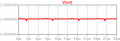
At the output of the photodiodes, signals are not getting subtracted
1587426031508.png
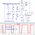
Graph 1
I1:

PULSE(165u 150u 3u 0 0 2u 8u 4)
165u = 15uA Data light + 150uA Background Light
150u = 0uA Data light + 150uA Background Light
I2:
150u = 150uA Background Light
- - - - - - - - - - - - - - - - - - - - - - - - - - - - - - - -
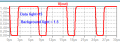
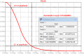
1587423218611.png
Graph 2
I1
:
PULSE(16.5u 1.5u 3u 0 0 2u 8u 4)
16.5u = 15uA Data light + 1.5uA Background Light
1.5u = 0uA Data light + 1.5uA Background Light
I2:
1.5u = 1.5uA Background Light
- - - - - - - - - - - - - - - - - - - - - - - - - - - - - - - -
 
Last edited:

Thread Starter

Saravana Vilashini M

Joined Apr 16, 2020
44
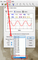
Thank you. Where is the option to set data light and background light in LTSpice?
Can you please send me the tutorial link?

According to my understanding, here background light is the noise which we are cancelling. If data light is fed to two photodiodes, the signal also gets cancelled. That's the reason we are giving data light = 0u to another photodiode.
Can we show the dark noise, shot noise, thermal noise in LTSpice?
Can you share me the LTSpice file?
 

Danko

Joined Nov 22, 2017
2,165
Last edited:

Danko

Joined Nov 22, 2017
2,165

Attachments

Last edited:

Thread Starter

Saravana Vilashini M

Joined Apr 16, 2020
44
Thank you so much. I can able to understand with your inputs.

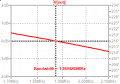
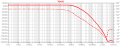
How to find the bandwidth for the circuit . I have chosen OPAMP of GBP = 4GHz. Feedback resistor chosen in 100k. I want to find total bandwidth using LTSpice?
 
Top