Transformer Winding

Thread Starter

DeepThinker

Joined Nov 26, 2018
28
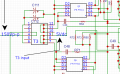
Hie everybody, I have a Transformer whose
input voltage = 5Vdc and Output voltage = 150Vp-p.
Frequency(f)= 384KHz
the above data has been verified in oscilloscope.
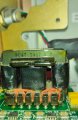
The primary side consists of two center tapped.
its a two E shape cores connected in the bobbin
its TDK E40 ferrite core , With Ae=1.49cm^2 and Bmax= 1800(considering) [Range is 1300-2000]
I know the formula to find Number of turns in Primary which is: Vin*10^8/(4*f*Bmax*Ae).
My doubt is, here the frequency is so high that using this formula, number of turns is not even equal to 1. How to find the number of turns in this configuration? can anyone help? Thank you in advance. I hope my question is clear to the readers
 

Ian0

Joined Aug 7, 2020
9,667
First, it ISN'T DC to AC. Transformers don't do DC, so I'll assume that the input is 384kHz.
Secondly, I don't know where you get the figures for Bmax. Ferrite never has a Bmax above 0.4Tesla.
Thirdly, Bmax is exactly what it says: the MAXIMUM value. There are several reasons that you don't want to operate it at just below saturation, the main one being CORE LOSS.
\(
Core loss \propto \hat{B}^{\frac{5}{2}}\cdot f^{\frac{5}{3}}
\)
The optimum value for B is when core-loss and copper-loss are about equal, and that depends on the power.
For 50W throughput, the optimum value of B is around 20mT, and that would give about 2 turns for a 5V primary, which would have to be several turns in parallel in order to get good core coverage.
 

Thread Starter

DeepThinker

Joined Nov 26, 2018
28
Thank you so much for your insights. If it's an inverter than it will convert dc to ac right . Bmax in ferrite core it's in the range (1300 to 2000) gauss yea it can be considered as Tesla also, I took it in gauss since in data sheet it was mentioned in gauss form. Can you tell me the formula about how did you got to 2 turns ?
 

Ian0

Joined Aug 7, 2020
9,667
It comes straight from Faraday's law:
\(
V=-N \cdot \frac {d \Phi}{dt}
\)
\(
\Phi = \frac{\int V dt}{N}
\)
\(
B=\frac {\Phi}{A_e}
\)
Knowing the limits of integration is the key to it. During one phase (i.e. when one transistor is on, for a push-pull design) B goes from -Bmax to +Bmax
so
\(
2B_{max}=\frac {V \cdot t}{N \cdot A_e}
\)
where t = half a cycle = 1/(2f)
\(
2B_{max}=\frac {V }{N \cdot A_e \cdot 2f}
\)
rearranging
\(
N=\frac {V}{4 Ae f B_{max}}
\)
It only works if everything is in SI units. Always work in base units, otherwise mistakes soon find their way in, for instance, don't forget that 1 square centimetre is 10^-4 square metres!

Core-loss is proportional to the peak-to-peak flux excursion, so, for a push-pull circuit there is twice as much B as there would be for a single-ended circuit like a flyback, for the same amount of Bmax. Twice as much B is 5.6 times as much loss.

It seems to me that 384kHz is a bit fast. Finding suitable diodes for 150V at 768kHz might not be so easy.
 

Thread Starter

DeepThinker

Joined Nov 26, 2018
28
It comes straight from Faraday's law:
\(
V=-N \cdot \frac {d \Phi}{dt}
\)
\(
\Phi = \frac{\int V dt}{N}
\)
\(
B=\frac {\Phi}{A_e}
\)
Knowing the limits of integration is the key to it. During one phase (i.e. when one transistor is on, for a push-pull design) B goes from -Bmax to +Bmax
so
\(
2B_{max}=\frac {V \cdot t}{N \cdot A_e}
\)
where t = half a cycle = 1/(2f)
\(
2B_{max}=\frac {V }{N \cdot A_e \cdot 2f}
\)
rearranging
\(
N=\frac {V}{4 Ae f B_{max}}
\)
It only works if everything is in SI units. Always work in base units, otherwise mistakes soon find their way in, for instance, don't forget that 1 square centimetre is 10^-4 square metres!

Core-loss is proportional to the peak-to-peak flux excursion, so, for a push-pull circuit there is twice as much B as there would be for a single-ended circuit like a flyback, for the same amount of Bmax. Twice as much B is 5.6 times as much loss.

It seems to me that 384kHz is a bit fast. Finding suitable diodes for 150V at 768kHz might not be so easy.

Thank you so much @Ian0
let me elaborate what I am doing here, I have attached two images consisting of the real transformer and its schematic. I am trying to prepare a transformer with same configuration, but I cant open the tapes to see the number of turns as it might damage it, I have all the inductance values also. in oscilloscope it is verified that 5vdc is fed to pin 9 and 10 and then as you can see two center tapped where it is going to drain then to source and source is going to ground(all these connections are verified by checking continuity). The transformer already exists where i/p = 5vdc and output= 150Vp-p from pin 3 and 4. and its frequency is also 384kHz. so the values which required to find Number of turns is present, but still not getting proper values in calculation.
 

Attachments

Ian0

Joined Aug 7, 2020
9,667
That’s a weird transformer. It has windings on all three limbs of the E, which means it has been designed to give a large amount of leakage inductance.
Did you measure the leakage inductance?
If not, you can measure it by measuring the inductance of the 150V winding with the two 5V windings shorted out.
How does it compare to the inductance of the 150V winding measured normally?
 

Thread Starter

DeepThinker

Joined Nov 26, 2018
28
That’s a weird transformer. It has windings on all three limbs of the E, which means it has been designed to give a large amount of leakage inductance.
Did you measure the leakage inductance?
If not, you can measure it by measuring the inductance of the 150V winding with the two 5V windings shorted out.
How does it compare to the inductance of the 150V winding measured normally?
Inductance measured with LCR meter
o/p side in pin 3 and 4 =1.91mH

primary side
pin 9 and 10 is connected through pcb , so no inductance for these pins.
for top center tapped
pin 10 and 11 = 22.5uH
pin 10 and 12 = 22.5uH
pin 11 and 12= 94.1uH

For down center tapped
pin 9 and 8 = 22.5uH
pin 9 and 7 = 22.5uH
pin 8 and 7= 94.1uH

these are the inductance readings
 
Top