 Facebook
 Google
 GitHub
 Linkedin
Hi everyone,
I'm working with a step-down transformer and have encountered a few surprising characteristics in its construction that I would like to understand better. I would really appreciate any insights into why it might be designed this way.
Transformer Specifications:
Primary Lead Color Code:
Voltage Test:
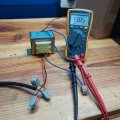
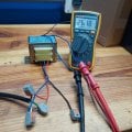
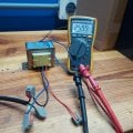
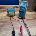
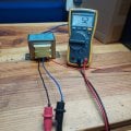
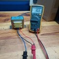
Using a variac, I applied 110V AC between the black and blue leads first and then between read and blue leads, but I measured 26V AC across the full secondary (12V–12V terminals) in both cases, which is interesting considering the resistance between each winding segments is not the same.
I understand that even though the DC resistance differs between Blue–Black and Blue–Red leads, the number of turns must be the same to result in the same voltage ratio on both configurations. This implies that the wire gauge and winding length are likely different between the two primary sections, perhaps due to thermal or cost optimization — but I’d like to know more about the reasoning behind such a design and if there any drawbacks or any usage considerations when applying 110V — for instance, is there any reason to prefer using Blue–Black over Blue–Red, or vice versa?
Thank you in advance!
I'm working with a step-down transformer and have encountered a few surprising characteristics in its construction that I would like to understand better. I would really appreciate any insights into why it might be designed this way.
Transformer Specifications:
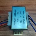
- Primary Voltage: 220V / 110V
- Secondary Voltage: 12V–0–12V
- Secondary Current Rating: 10A
Primary Lead Color Code:
- Black
- Blue (center tap)
- Red
- Black to Blue: 5 ohms
- Blue to Red: 10 ohms
- Black to Red: 15 ohms
Voltage Test:
Using a variac, I applied 110V AC between the black and blue leads first and then between read and blue leads, but I measured 26V AC across the full secondary (12V–12V terminals) in both cases, which is interesting considering the resistance between each winding segments is not the same.
I understand that even though the DC resistance differs between Blue–Black and Blue–Red leads, the number of turns must be the same to result in the same voltage ratio on both configurations. This implies that the wire gauge and winding length are likely different between the two primary sections, perhaps due to thermal or cost optimization — but I’d like to know more about the reasoning behind such a design and if there any drawbacks or any usage considerations when applying 110V — for instance, is there any reason to prefer using Blue–Black over Blue–Red, or vice versa?
Thank you in advance!
Attachments
-
 305.3 KB Views: 8
 -
 297 KB Views: 8
 -
 292.6 KB Views: 5
 -
 301.5 KB Views: 6
 -
 295.2 KB Views: 6
 -
 292.9 KB Views: 9
 -
 183.8 KB Views: 9


