Transformer Secondary Windings Identification

Thread Starter

smachado

Joined Feb 4, 2018
10
Greetings,

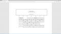
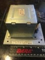
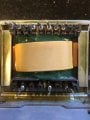
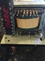
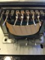
Can someone please assist with making sense of the secondary winding taps on this transformer? I have an image of the continuity and measured voltages attached. It does not seem to make easy sense to me. Thoughts on the secondary windings?

Thanks, Scott
 

Attachments

Ylli

Joined Nov 13, 2015
1,086
I interpret you have continuity between the first and second tap. You also have continuity between 3, 4, 5, 6, & 7. Is there continuity between 1&2 and 3-7?
 

Thread Starter

smachado

Joined Feb 4, 2018
10
Hello,
No. There is no continuity between taps 1&2 and 3-7.
Thanks,
Scott
I interpret you have continuity between the first and second tap. You also have continuity between 3, 4, 5, 6, & 7. Is there continuity between 1&2 and 3-7?
 

olphart

Joined Sep 22, 2012
114
Silly me, I use a 12VAC (several amp) transformer, connect it to the highest resistance winding and log the ratios to everywhere else.
I can roughly(!) guess ampacity by ratio & resistance.
 
Last edited:
Man, I'm terrible at drawing free hand with a mouse. But I see this:View attachment 154686
I agree on both things ;-) I also seriously doubt I'd do as well as you did with the freehand mouse drawing.
Now with actual DC resistance numbers and a VA rating for this thing we might even guess the ratings of each of the windings.
OP: If you want help with estimating the ratings of the windings: If the windings are visible at all and you can guesstimate the position of each winding in the bobbin or at least the order in which they are wound will help put a sanity check on the results. Better yet if you have a vernier and can measure the wire diameters... and maybe make a guess of the insulation thickness if the wires are small (<0.015")
 

Thread Starter

smachado

Joined Feb 4, 2018
10
I agree on both things ;-) I also seriously doubt I'd do as well as you did with the freehand mouse drawing.
Now with actual DC resistance numbers and a VA rating for this thing we might even guess the ratings of each of the windings.
OP: If you want help with estimating the ratings of the windings: If the windings are visible at all and you can guesstimate the position of each winding in the bobbin or at least the order in which they are wound will help put a sanity check on the results. Better yet if you have a vernier and can measure the wire diameters... and maybe make a guess of the insulation thickness if the wires are small (<0.015")
Hello,

After reveiwing the hand drawing (very nice) I was able to make sense of the taps. I have not encountered a non-sequential physical layout on the few transformers I have worked with.

The drawing makes it look/seem like a std set of secondary windings now. Thank you for the drawing.

I have attached an updated diagram (out of order taps) that better represents the taps.
Transformer Taps - 02.png
Regarding ratings , I believe the windings are 18 gauge. I do not know what the VA rating is but here are other specs:

Weight: 10lbs
Size: 3.75" x 3.25" x 3.25"

I believe that I can use the transformer as follows as long as the VA rating (unknown) is not surpased:

Secondary A - 1-2 - 19.5v
Secondary B - 6-7 - 100v
Secondary C - 6-5 - 50v
Secondary D - 5-7 - 50v
Secondary E - 3-4 - 42v
Secondary F - 3-5 - 21v
Secondary G - 5-4 - 21v

Thank you for the info to date. If you can guestimate the VA rating, I'd appreciate it. I will also do my best at providing any additional information needed.

Thx,
Scott
 

MisterBill2

Joined Jan 23, 2018
18,176
As has been mentioned, the resistance readings can be quite useful in discovering which are center taps. And that freehand mouse drawing wa almost as good as my freehand pencil drawings, so don't be embarrassed about it. Evaluating a transformer is a lot easier if the windings are visible, but it seems to have been figured out very well. It seems that others were able to offer the same help but sooner than me. I was just very busy this past few days.
 

Ylli

Joined Nov 13, 2015
1,086
Shows you what you need to measure (or estimate) to determine the transformers core cross sectional area. Then: (5.58 x core CSA)² = Volt*Amps capacity.

Otherwise, basic rule of thumb is 20 W per pound.
 
Shows you what you need to measure (or estimate) to determine the transformers core cross sectional area. Then: (5.58 x core CSA)² = Volt*Amps capacity.

Otherwise, basic rule of thumb is 20 W per pound.
Which would make this a 200VA transformer. I find that hard to believe.
These rules of thumb make some very large assumptions about the design of the transformer and as this looks to be a special, the standard design parameters may not have applied. I'm not sure that even a temp rise test under load would yield a reliable result. This may be a class h, or a class a transformer and the difference is not insignificant.
I guess a worst case assumption of class a will at least provide a conservative (and hopefully non destructive) result.
 
Hello,

Meant to attach these for visual reference...

Thanks,
Scott
Hmmm. This changes things a bit. If I am seeing this correctly, there are two wires terminated on the centre tap pin so there are some interwinding connections made within the windings themselves. There also appears to be two wires terminated on each of pins 3 and 4 suggesting that those windings are wound bifilar. As they are the lower voltage ct winding I would have expected them to have a significantly lower resistance than the 100V ct winding which also appears to be a narrower gauge wire than the bifilar 40V ct winding.
Just as a quick sanity check, when you short the leads of your ohm meter, what reading do you get? For this type of resistance measurement it is often better to use a known current and measure the voltage drop but do it quickly before the temperature rises and the resistance changes (which it can do to a surprising degree and quickly).
You are correct in that you must not exceed the VA rating of the transformer (for a sustained period, a brief overload is not typically a problem, you need that to pop a fuse :)) but you must also not exceed the current rating of individual secondary windings. If you do not use a winding it does not mean the VA from that winding is then available from another and on top the other windings original rating. So an estimate for each winding would still be a good idea but first, can we double check your resistance measurements please?
 

ericgibbs

Joined Jan 29, 2010
18,766
hi Scott.
Do you know which type of equipment the transformer was originally powering.??

Eric
BTW: did a web search for that Toshiba code, inconclusive.
 

MisterBill2

Joined Jan 23, 2018
18,176
What it looks like to me is that it was, or was intended for, was a power supply for an older VCR power supply. Those usually had several voltages, one for the display, one for the motors, and one for the electronics in general, and then a higher voltage supply for the electronic tuning for the TV receiving tuner. It may also be intended for an all-in-one radio-cassette player box, although they don't often have a PCB mounted transformer..

The pins with two smaller wires may be taps on a higher voltage winding, sometimes that is done to save money, instead of having separate windings. So I am thinking that the mouse-hand drawing may be a close representation of how it really is.
 
Top