 Facebook
 Google
 GitHub
 Linkedin
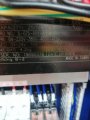
I am a bit confused about the operation of this transformer. The transformer you see here is a control transformer, and is currently wired to step down from 415v to 24 and 11.5 V. I am trying to use a switching power supply to convert Ac 240 v to a 5V dc. Because I need a peculiar 5v dc as my output, the only power supply I could find had 240 AC as my input. The system, the transformer is attached to is a 3 phase system (no neutral) and I was thinking of using 1 phase out of the three phase as my input and adding a extra neutral for my power supply. However, when I started measuring the voltage across the transformer (primary), I was a bit confused. The two black wires u see in image (primary) are each getting 210v each, making it (415v line to line). When I measured the voltage (primary) between 0 and 230 I was getting 230v, and when I measured the voltage between 0 and 380, I measured 380v. Bit confusing as it is a input side and 0v tapping is actually feeding in 210 v for the primary side. So rather than using a extra neutral I just used the 220v tapping as my neutral from the primary side. I am assuming there a taps in primary side adjusting voltage.
Mod: highlighted one image.
Mod: highlighted one image.
Attachments
-
 3.3 MB Views: 13
 -
 3.2 MB Views: 12
 -
 3.5 MB Views: 13
 -
 1.2 MB Views: 10
Last edited by a moderator:


