There is no easy answer. The thicker gauge wires are likely the primary but you make no mention of inverter type or voltages? The lighter gauge wires are likely the secondary and possibly center tapped. You have what looks to be a meter sitting there, have you taken any resistance readings? How to connect the transformer depends on what you want to do with the transformer?
There is no easy answer. The thicker gauge wires are likely the primary but you make no mention of inverter type or voltages? The lighter gauge wires are likely the secondary and possibly center tapped. You have what looks to be a meter sitting there, have you taken any resistance readings? How to connect the transformer depends on what you want to do with the transformer?
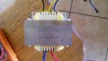
No matter which two wires I connect to a 12v battery it shorts out the two thick wires went to heatsinks and the three thin ones just went on te circuit board as well
The idea is to apply a low voltage AC and not direct mains. Low voltage AC or a pulsed DC to what should be the primary side assuming this transformer is out of an inverter.
Aren't you guys forgetting this was from an inverter? the "primary" would only be rated for 24V(according to T/S) and probably the one with three wires. And center tapped like Reloadron said, from a push-pull driver. The "secondary" would be the two wire one and a high voltage. Wouldn't it ?
Aren't you guys forgetting this was from an inverter? the "primary" would only be rated for 24V(according to T/S) and probably the one with three wires. And center tapped like Reloadron said, from a push-pull driver. The "secondary" would be the two wire one and a high voltage. Wouldn't it ?
I gave that some thought. Problem I have is looking at the picture there looks to be two heavy leads and only two. Figuring inverter I wanted to make that the higher current side primary. I did ask the OP to try a few basic DC resistance measurements which he apparently didn't do but did try mains power to the existing leads and managed to trip a breaker. Finally "Mains Voltage" is always an interesting term. Like I would know what his "mains voltage" is? I know yours only because I know you are down the road from me.
I haven't a clue what this inverter was either? What maybe 12 or 24 VDC to 120 or 240 VAC? True Sine or Modified Sine? Nice looking transformer though and I like the wire colors.
Hi its 24dc to 220ac I tried DC measurements but it imediatly shorts out with eighter windings , next try is going to be low ac voltage input .... Somehow no idea how I'm going to make 220 lower ,its a hobby and would be a shame to waste such an Awsome transformer
 Facebook
 Google
 GitHub
 Linkedin
 1.4 MB Views: 31
")


