If you have used a varicap in place of a capacitor you need to show the schematic of how it is connected, the part number of the varicap and the tuning voltage range you are using. Using a varicap with high amplitude signals can cause problems.
At that frequency you should at least use copper clad boards. Everything has to have short leads (and clip all tails).....so no sockets. Solder all connections. Lay your resistors down.
I think i get what you are trying to imply. The long legs of components are transmitting too right. Your idea sounds plausible so I will give it a go tomorrow.Thanks!
If you have used a varicap in place of a capacitor you need to show the schematic of how it is connected, the part number of the varicap and the tuning voltage range you are using. Using a varicap with high amplitude signals can cause problems.
If you have used a varicap in place of a capacitor you need to show the schematic of how it is connected, the part number of the varicap and the tuning voltage range you are using. Using a varicap with high amplitude signals can cause problems.
Hi Albert,
My concern was that the OP has not done anything to ensure that the varicap does not become forward biased which is why I asked for a schematic of how it was wired. Also as the circuit is only powered with 3 volts this is very low for the tuning voltage for a varicap. This is also why I asked fot the part number of the varicap so I could find the data sheet for it.
Edit. I have just seen the block diagram of the BA1404 that bertus posted. I had assumed that the varicap had been used to tune the output power amplifier but if it is only being used in the oscillator then it will probably not be a problem.
The circuit the TS was copying did not use a varicap. RF tuning was done by an adjustable ferrite cored coil. The TS has substituted an air cored coil with tuning by a variable capacitor which I believe the TS refers to as a 'varicap'. There is no diode of any type visible on the photograph of the TS board layout.
i agree with post #20 that high Q inductors are needed, there should be two air core inductors but i only see one.
about construction - leads are short enough, layout and construction technique is... acceptable
i would say:
- PCB is very badly oxidized, i would have cleaned it to a shine before starting soldering.
- there is some excess solder and flux on the board (even bleeding through to the other side of the board), this should be cleaned
- several pads are missing, probably burned off
- i am not fan of IC sockets, specially for this but - it may have been a good thing in this case given soldering skill (hope IC was inserted afterwards and not subjected to heat).
30 years ago i was having hard time getting real varicap diodes but Base-Collector section of a small signal transistor worked a treat.
i agree with post #20 that high Q inductors are needed, there should be two air core inductors but i only see one.
about construction - leads are short enough, layout and construction technique is... acceptable
i would say:
- PCB is very badly oxidized, i would have cleaned it to a shine before starting soldering.
- there is some excess solder and flux on the board (even bleeding through to the other side of the board), this should be cleaned
- several pads are missing, probably burned off
- i am not fan of IC sockets, specially for this but - it may have been a good thing in this case given soldering skill (hope IC was inserted afterwards and not subjected to heat).
Yes, I didn't solder the ic base with the BA1404 on board. Also, what are high Q inductors? High inductance?
30 years ago i was having hard time getting real varicap diodes but Base-Collector section of a small signal transistor worked a treat.
Hi Albert,
My concern was that the OP has not done anything to ensure that the varicap does not become forward biased which is why I asked for a schematic of how it was wired. Also as the circuit is only powered with 3 volts this is very low for the tuning voltage for a varicap. This is also why I asked fot the part number of the varicap so I could find the data sheet for it.
Edit. I have just seen the block diagram of the BA1404 that bertus posted. I had assumed that the varicap had been used to tune the output power amplifier but if it is only being used in the oscillator then it will probably not be a problem.
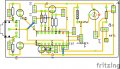
So, after all your suggestions, I think I might be able to remake it for better performance. I will make a pcb on Fritzing today based on the following changes:
1-All the resistors laid down.
2-Will prevent long distance connections.
Also, do you think I should add copper pour or not. Since it won't be connected anywhere. I don't think that should pose a problem. Also, I will post the pcb layout with silkscreen here for you all verify it. Really glad this forum is so interactive. Looking forward to learn a great deal from you guys.
Hey, on the last note, I noticed I have a 5mm Ferrite core lying around and currently I have 22SWG copper wire. I think they might act as a high Q inductor. Please tell me how to use both along with a varicap for I don't have any idea how to make ferrite cored inductors.
You might want to take a stab in a different direction. The 38 kHz and 19 kHz from the stereo multiplex circuit and their harmonics are getting into the transmitter via the modulation input to the transmitter causing multiple sidebands spaced 38 kHz apart above and below the carrier frequency. If that is the case, then these unwanted sidebands (all of which will be frequency modulated) will not be as strong as the desired signal.
Remember, this chip is not broadcast quality and they took a lot of shortcuts.
Your receiver might be too close to the transmitter. Try moving your receiver a few meters or more away from the transmitter and see whether the undesired signals fade out way before the desired signal fades out.
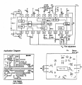
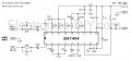
The pilot signal is filtered with a single pole filter which probably doesn't do much to the 19 kHz pilot signal which is very close to the upper frequency of the MPX signal. You might improve the signal by adding some poles to the low pass filter on pin 12, which is a .001 uf and some resistance in series with the MPX out and Pilot signals at the moment.
Keep in mind that this chip is nothing near "broadcast quality".
You might want to take a stab in a different direction. The 38 kHz and 19 kHz from the stereo multiplex circuit and their harmonics are getting into the transmitter via the modulation input to the transmitter causing multiple sidebands spaced 38 kHz apart above and below the carrier frequency. If that is the case, then these unwanted sidebands (all of which will be frequency modulated) will not be as strong as the desired signal.
Remember, this chip is not broadcast quality and they took a lot of shortcuts.
Your receiver might be too close to the transmitter. Try moving your receiver a few meters or more away from the transmitter and see whether the undesired signals fade out way before the desired signal fades out.
The pilot signal is filtered with a single pole filter which probably doesn't do much to the 19 kHz pilot signal which is very close to the upper frequency of the MPX signal. You might improve the signal by adding some poles to the low pass filter on pin 12, which is a .001 uf and some resistance in series with the MPX out and Pilot signals at the moment.
Keep in mind that this chip is nothing near "broadcast quality".
Apparently, I am using a 5cm antenna currently with 3.6V input and the range is not very good. The transmission is not received as soon as I move away. This is for all frequencies

 Facebook
 Google
 GitHub
 Linkedin