Also wanted to ask this. In my previous attempt making this circuit, when I used 1% Metal film resistors instead of carbon film ones, the static was much greater. I had placed them close to each other and vertically. Now you all are saying to clip the legs. I wanted to know if placed horizontally, will it be better to use those metal film resistors again. Needless to say, they are mentioned on the circuit providing website. What should I do?
ok ..so you're only using it as as a voltage reducer. Also, about using a high Q coil, I have 3 values, 7uH,15uH and 100uH. There's also 150uH. Which one should I use?
Varicaps can cause the kind of disrortion you described if the RF voltage waveform across it is large enough to cause a significant change in capacitance.
You might want to test for this by temporarily replacing L1 with a hand wound inductor that you can adjust by complessing and spreading it and changing the varicap to a fixed capacitor.
Varicaps can cause the kind of disrortion you described if the RF voltage waveform across it is large enough to cause a significant change in capacitance.
You might want to test for this by temporarily replacing L1 with a hand wound inductor that you can adjust by complessing and spreading it and changing the varicap to a fixed capacitor.
I have been using it. Was successful in finding the transmission frequency by lengthening or shortening it. But even after setting an ideal length of coil for required frequency, the song is transmitted so badly that it is beyond recognition.
Do you mean that there is no varicap in the circuit now? If there is no varicap and you still have the problem, then it is agreed the varicap is not the source of the problem.
Do you mean that there is no varicap in the circuit now? If there is no varicap and you still have the problem, then it is agreed the varicap is not the source of the problem.
Can I suggest that you stop calling the trimmer capacitor which you are using a 'varicap'. To folk on here 'varicap' means a semiconductor diode used as a variable capacitor by varying the reverse voltage across it.
Can I suggest that you stop calling the trimmer capacitor which you are using a 'varicap'. To folk on here 'varicap' means a semiconductor diode used as a variable capacitor by varying the reverse voltage across it.
So after a lot of googling, I found this schematic. https://elect.wikispaces.com/Low+power+FM+stereo+transmitter
The quality is good now, but I am not getting the "Stereo Effect" in its transmission. Also, what I am observing is that the transmission volume is low and the left channel's audio is being loudly transmitted in both channels on the receiver side while the right channel is lowly transmitted in both channels.
I checked the channels using this video:
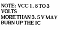
Also, just so you know I am still using my lithium battery currently at 3.4V, so I have not used the power circuit as shown on the schematic of the link I provided.
So, now my final aim is to increase transmission volume and get a true stereo output.

 Facebook
 Google
 GitHub
 Linkedin